Vibration dampening device for the manufacture of a rotor

Active Publication Date: 2014-06-12
SN DETUDE & DE CONSTR DE MOTEURS DAVIATION S N E C M A
View PDF16 Cites 2 Cited by
  • Summary
  • Abstract
  • Description
  • Claims
  • Application Information

AI Technical Summary

Benefits of technology

The invention aims to provide a solution for reducing and preventing vibrations during welding of rotational friction discs in compressors or turbines. The solution is simple, effective, ergonomic, and economical, and can be applied regardless of any uncontrolled coaxial misalignments of the discs. The patent describes a method involving using clamps to dampen the vibrations generated during the welding process.

Problems solved by technology

However, it generates high-frequency and high-intensity vibrations, which can favour the formation of cracks due to fatigue with a large number of cycles, in particular on thin zones as well as in the hubs of these discs.
However, when the diameter of the hubs is substantial, the axial force applied on the rings is substantial.
The rings are furthermore difficult to remove at the end of welding, and risk scratching the internal surface of the hubs.
Finally, the hubs of the discs generally present different inner diameters and uncontrolled coaxial misalignments, therefore random, which are intrinsic to the process of welding via friction and which can reach 0.3 mm, which renders the use of these rings very delicate.

Method used


Image

  • Vibration dampening device for the manufacture of a rotor
  • Vibration dampening device for the manufacture of a rotor
  • Vibration dampening device for the manufacture of a rotor

Examples


Embodiment Construction

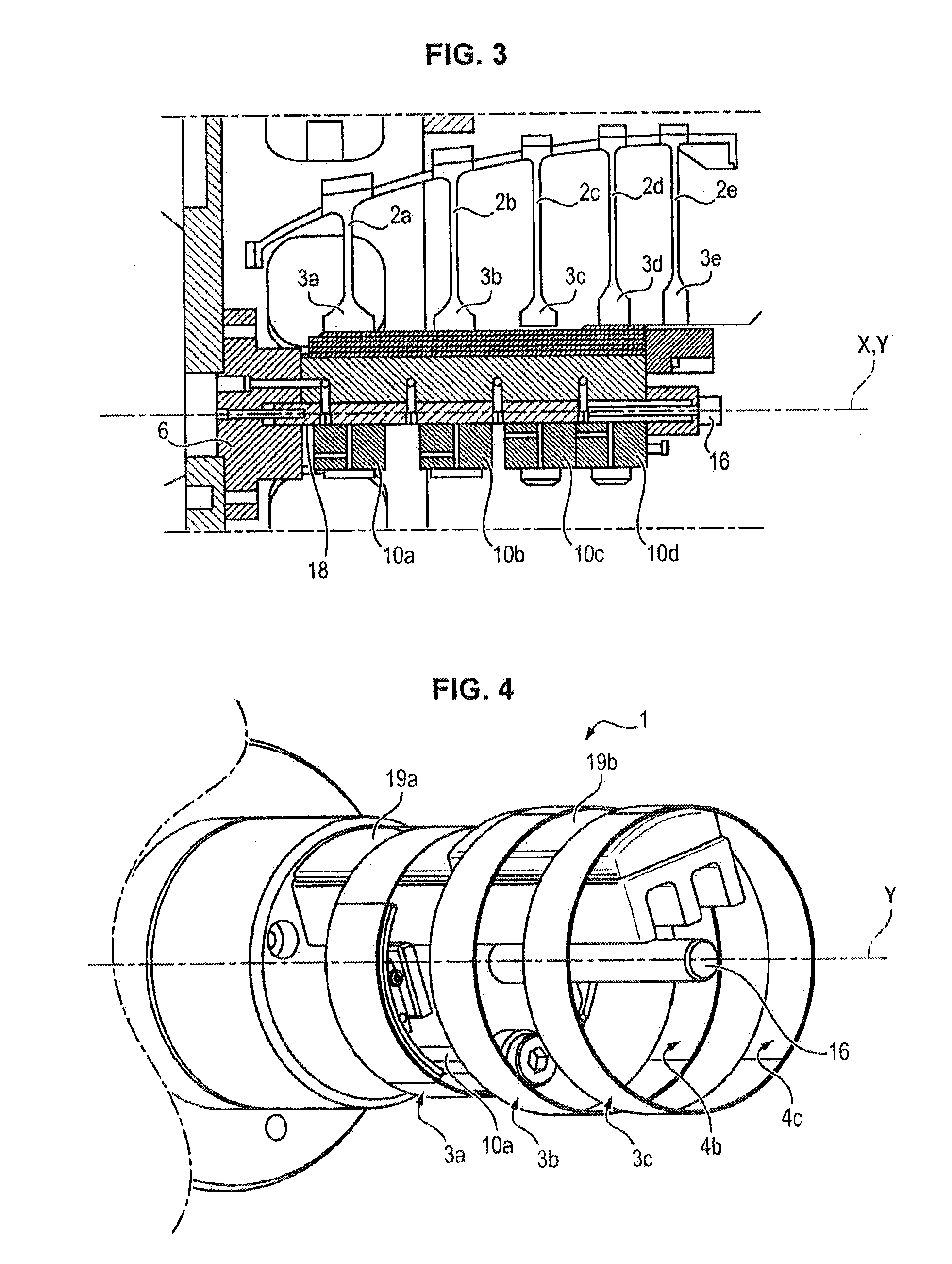
[0040]In what follows, the invention shall be described more particularly in the framework of the assembling of the discs 2a-2e (or compression stages) of a compressor, in particular high pressure. This is not however a limitation, in that the invention applies mutatis mutandis to the assembly of expansion stages of a turbine.

[0041]The compressor comprises several discs 2 (or compression stages), here five discs 2a-2e, each comprising a disc that can be vaned, mobile in rotation around its main axis X, and a fixed impeller. The discs are either provided with peripheral grooves wherein vanes are nested, or with integrally vaned discs.

[0042]The discs 2a-2e include hubs 3a-3e of a generally cylindrical revolution shape and extend coaxially to an axis of rotation X of the compressor. Each hub 3a-3e comprises an internal surface 4a-4e (or bore) and an external surface from which the vanes radially extend.

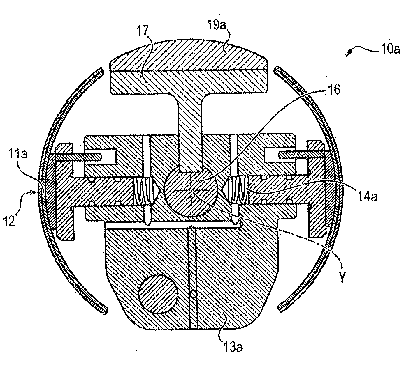
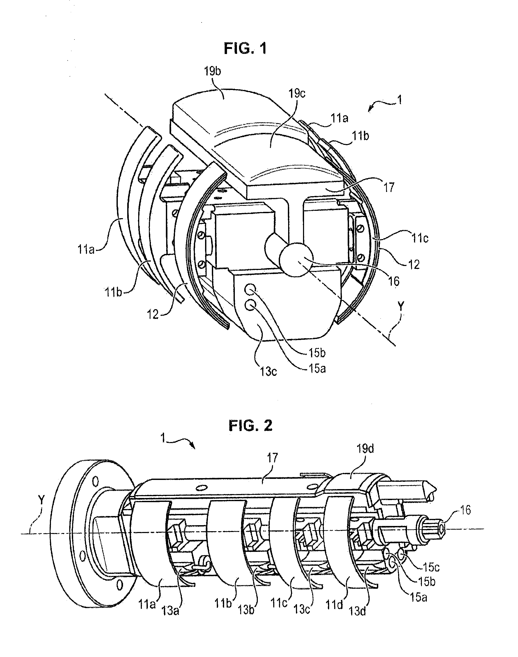
[0043]The vibration dampening device 1 has a main direction extending along a longit...


PUM

PropertyMeasurementUnit
Timeaaaaaaaaaa
Timeaaaaaaaaaa
Viscoelasticityaaaaaaaaaa

Abstract

The invention relates to a vibration dampening device (1) for the manufacture by rotational friction welding of a turbomachine rotor, said rotor comprising at least one first disc (2a) and a second disc (2b) each comprising a hub (3a, 3b) having an internal surface (4a, 4b), with the device (1) comprising at least one first clamping device (10a) configured to be positioned coaxially to the hub (3a) of the first disc (2a), comprising a pair of radially opposite jaws (11a) suited to come into contact with the internal surface (4a) of said hub (3a) of the first disc (2a).

Description

FIELD OF THE INVENTION[0001]This invention relates to a method for assembling the discs of a rotor of a turbomachine by rotational friction welding and a vibration dampening device for hubs of discs during their assembly via this method.TECHNOLOGY BACKGROUND[0002]A compressor, in particular high pressure, comprises one or several rotating discs (rotor), vaned or not and one or several fixed impellers (rectifier stages).[0003]A turbine, in particular high pressure, comprises several rotating discs (rotor), vaned or not, and one or several fixed impellers (nozzle stages).[0004]The rotating discs generally include peripheral grooves wherein vanes are nested, or are carried out in a single piece with the vanes, which are then machined on the periphery of the discs (the discs of this type are called integrally vaned discs).[0005]The different discs can be assembled coaxially by bolting, by electron beam welding or, by rotational, inertial or pilot friction welding.[0006]The welding via r...

Claims


Application Information

Patent Timeline
IPC IPC(8): B23K20/12B23K37/04
CPCB23K37/04B23K20/122B23K37/0531B23K20/129B23K2101/001B23K20/12B23K37/0435F01D25/285
Inventor BOUR, JEAN-LUC
Owner SN DETUDE & DE CONSTR DE MOTEURS DAVIATION S N E C M A
Why Eureka
Try Eureka