
High aspect ratio daylight collectors

a daylight collector and high aspect ratio technology, applied in the field of daylighting and to light collectors, can solve the problems of various drawbacks of certain currently known devices and methods for receiving daylight into daylighting devices, and achieve the effect of increasing the amount of light captured

Active Publication Date: 2014-06-12
SOLATUBE INT INC
View PDF4 Cites 23 Cited by
  • Summary
  • Abstract
  • Description
  • Claims
  • Application Information

AI Technical Summary

Benefits of technology

The patent describes a device and process for collecting and directing daylight into a building interior. The device includes a tube with a reflective interior surface and a light collector base aperture. It also includes a prismatic element and an infrared control element to increase the amount of light captured. The device can be installed over an opening in a roof of a building. The technical effects of the patent include improved lighting in buildings, increased energy efficiency, and improved comfort for occupants.

Problems solved by technology

Certain currently known devices and methods for receiving daylight into a daylighting device suffer from various drawbacks.

Method used


Image

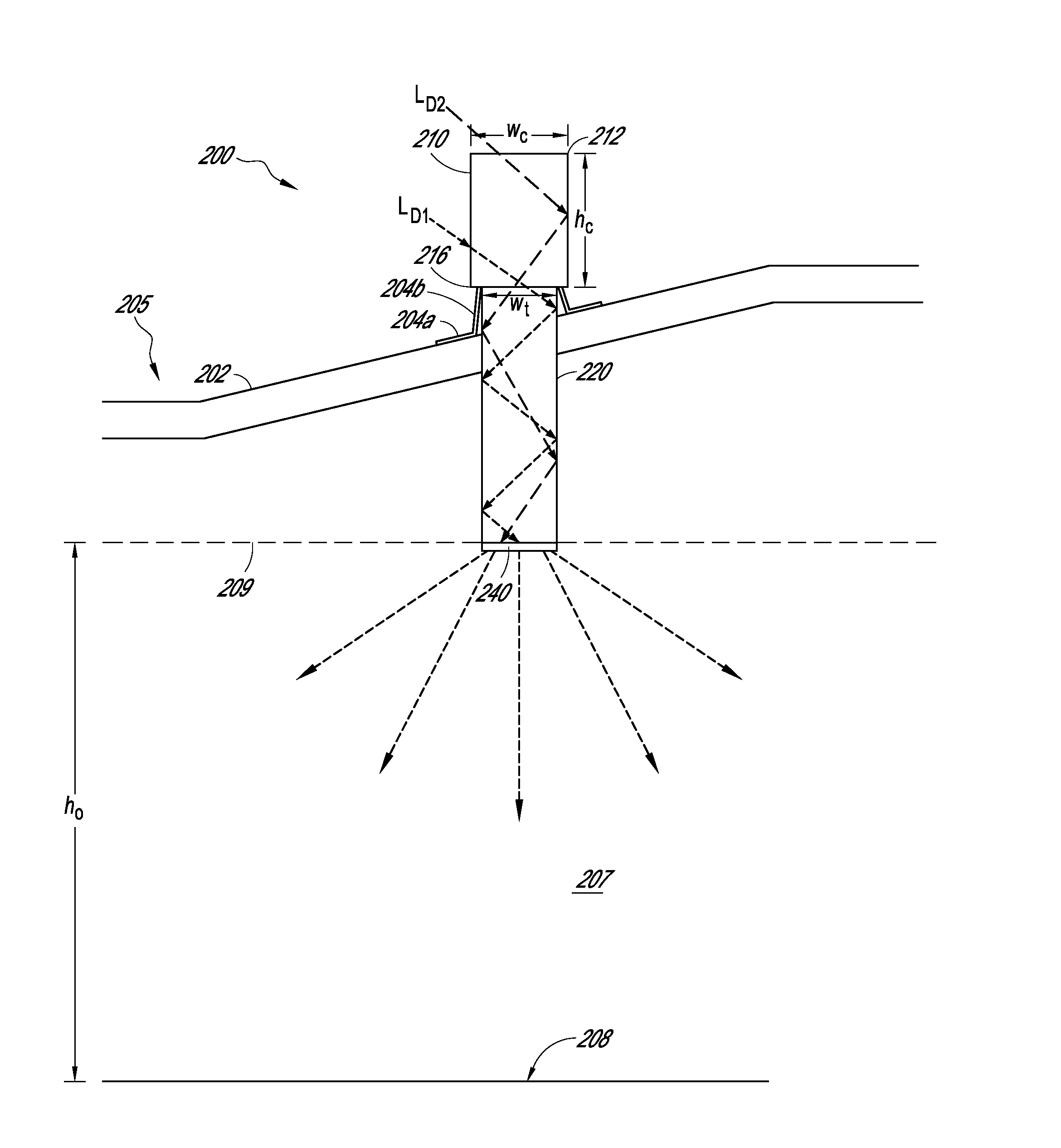
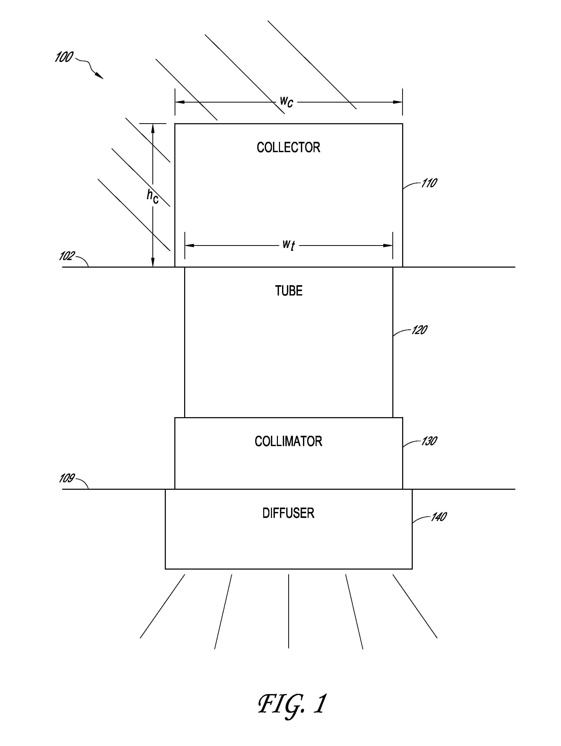
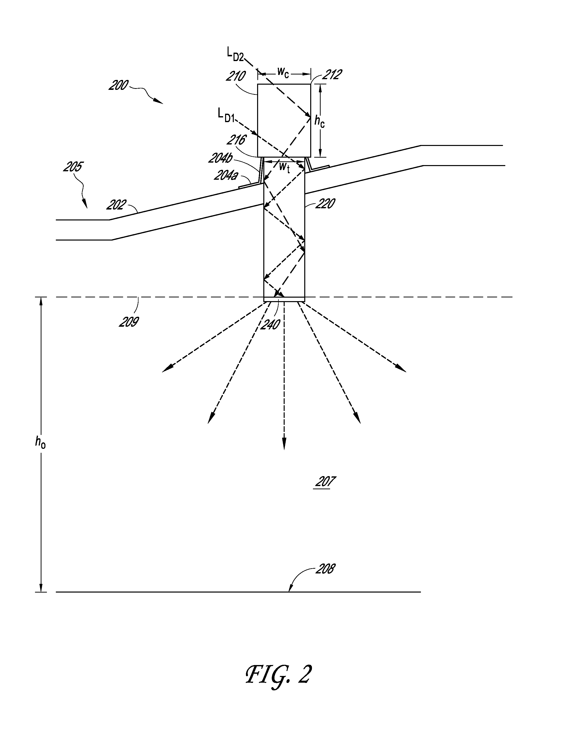
  • High aspect ratio daylight collectors
  • High aspect ratio daylight collectors
  • High aspect ratio daylight collectors

Examples


embodiment 1

[0165]2. The device of embodiment 1, wherein the height of the vertical portion is greater than the width of the collector base aperture.

embodiment 2

[0166]3. The device of embodiment 2, wherein an aspect ratio of the height of the vertical portion to the width of the collector base aperture is greater than 1.2 to 1.

[0167]4. The device of any of embodiments 1-3, wherein the top cover portion is substantially flat.

[0168]5. The device of any of embodiments 1-4, wherein the top cover portion comprises a dome-shaped surface.

[0169]6. The device of any of embodiments 1-5, wherein the top cover portion comprises a cone-shaped surface.

[0170]7. The device of any of embodiments 1-6, wherein the vertical portion comprises a plurality of vertically-arranged segments, including a top segment, a middle segment, and a bottom segment.

embodiment 7

[0171]8. The device of embodiment 7, wherein the top segment is associated with first optical elements having first light-turning characteristics and the middle portion is associated with second optical elements having second light-turning characteristics.

[0172]9. The device of any of embodiments 7-8, wherein the bottom segment is not associated with light-turning optical elements.

[0173]10. The device of any of embodiments 7-9, wherein the top, middle, and bottom segments are each approximately 5 to 10 inches in height.

[0174]11. The device of any of embodiments 7-10, wherein the top, middle, and bottom segments are each a uniform height.

[0175]12. The device of any of embodiments 7-11, wherein the reflector is at least partially transparent with respect to infrared light.

[0176]13. The device of any of embodiments 7-12, wherein the vertical portion is substantially cylindrically shaped.


PUM

PropertyMeasurementUnit
aspect ratioaaaaaaaaaa
heightaaaaaaaaaa

Abstract

Lighting devices and methods for providing daylight to the interior of a structure are disclosed. Some embodiments disclosed herein provide a daylighting device including a tube having a sidewall with a reflective interior surface, a light collecting structure, and a light reflector positioned to reflect daylight into the light collector. In some embodiments, the light collector is associated with one or more light-turning and / or light reflecting structures configured to increase the amount of light captured by the daylighting device. Optical elements may allow for the absorption and / or selective transmission of infrared light away from an interior of the daylighting device.

Description

BACKGROUND[0001]1. Field[0002]This disclosure relates generally to daylighting and to light collectors used in daylighting systems.[0003]2. Description of Related Art[0004]Daylighting systems typically include windows, openings, and / or surfaces that provide natural light to the interior of a building. Examples of daylighting systems include skylights and tubular daylighting device installations. Various devices and methods exist for receiving daylight into a daylighting device. Certain currently known devices and methods for receiving daylight into a daylighting device suffer from various drawbacks.SUMMARY[0005]Lighting devices and methods for providing daylight to the interior of a structure are disclosed. Some embodiments disclosed herein provide a daylighting device including a tube having a sidewall with a reflective interior surface, a light collecting assembly, and a light reflector positioned to reflect daylight into the light collector. In some embodiments, the light collect...

Claims


Application Information

Patent Timeline
Patent Type & Authority Applications(United States)
IPC IPC(8): G02B17/00
CPCF21S11/00G02B17/00F21S11/007G02B5/04G02B5/08Y10T29/49826E04D13/033
Inventor JASTER, PAUL, AUGUST
Owner SOLATUBE INT INC
Learn More