Daylight sensing arrangement for a hybrid luminaire

a hybrid luminaire and daylight sensing technology, applied in the field of daylight sensing arrangement of hybrid luminaires, can solve the problems of easy to find the right position and method to accurately measure the sunlight parameters, and achieve the effect of accurately measuring the sunlight parameters

Inactive Publication Date: 2016-04-26
SIGNIFY HLDG BV +1
View PDF7 Cites 6 Cited by
  • Summary
  • Abstract
  • Description
  • Claims
  • Application Information

AI Technical Summary

Benefits of technology

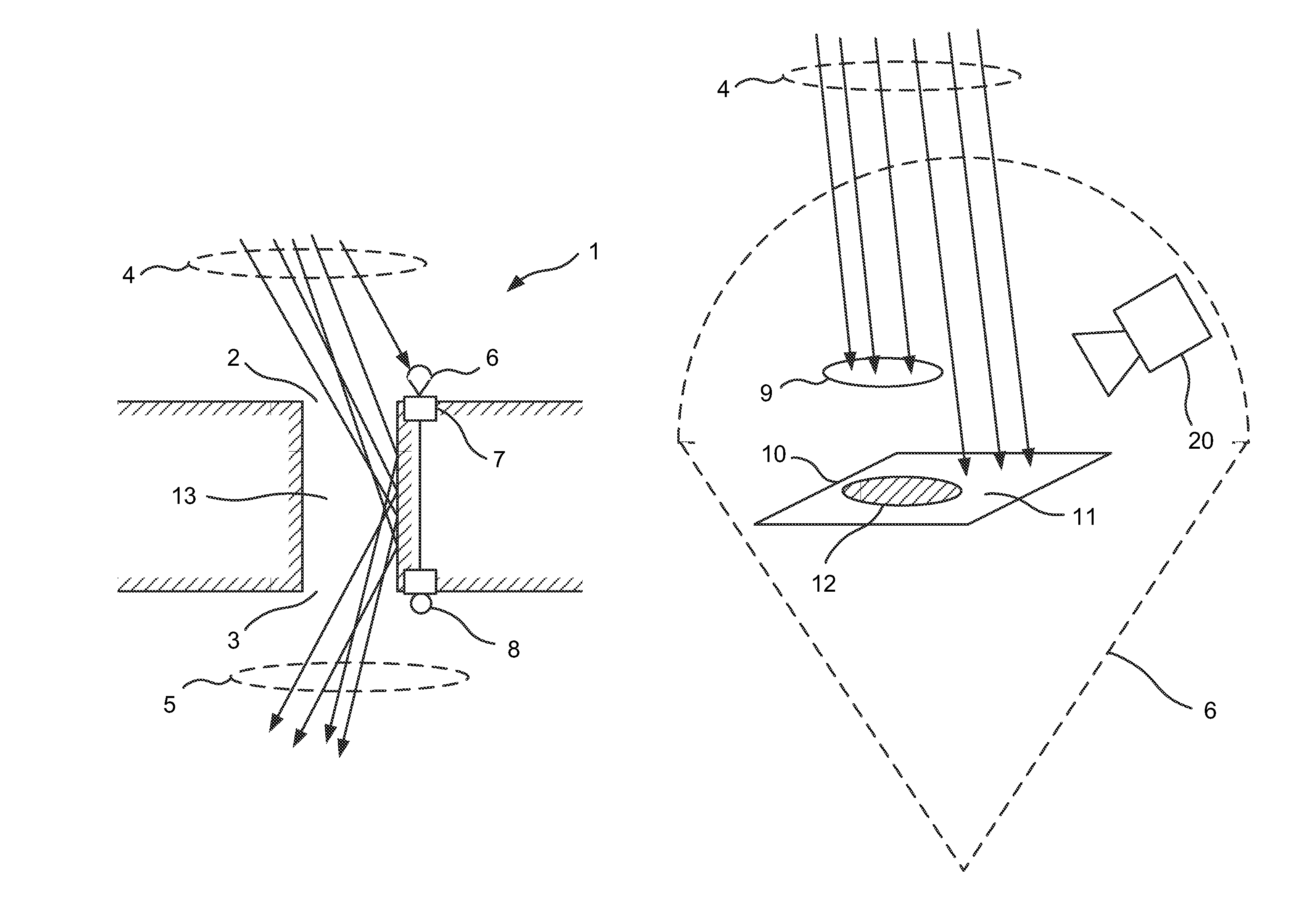
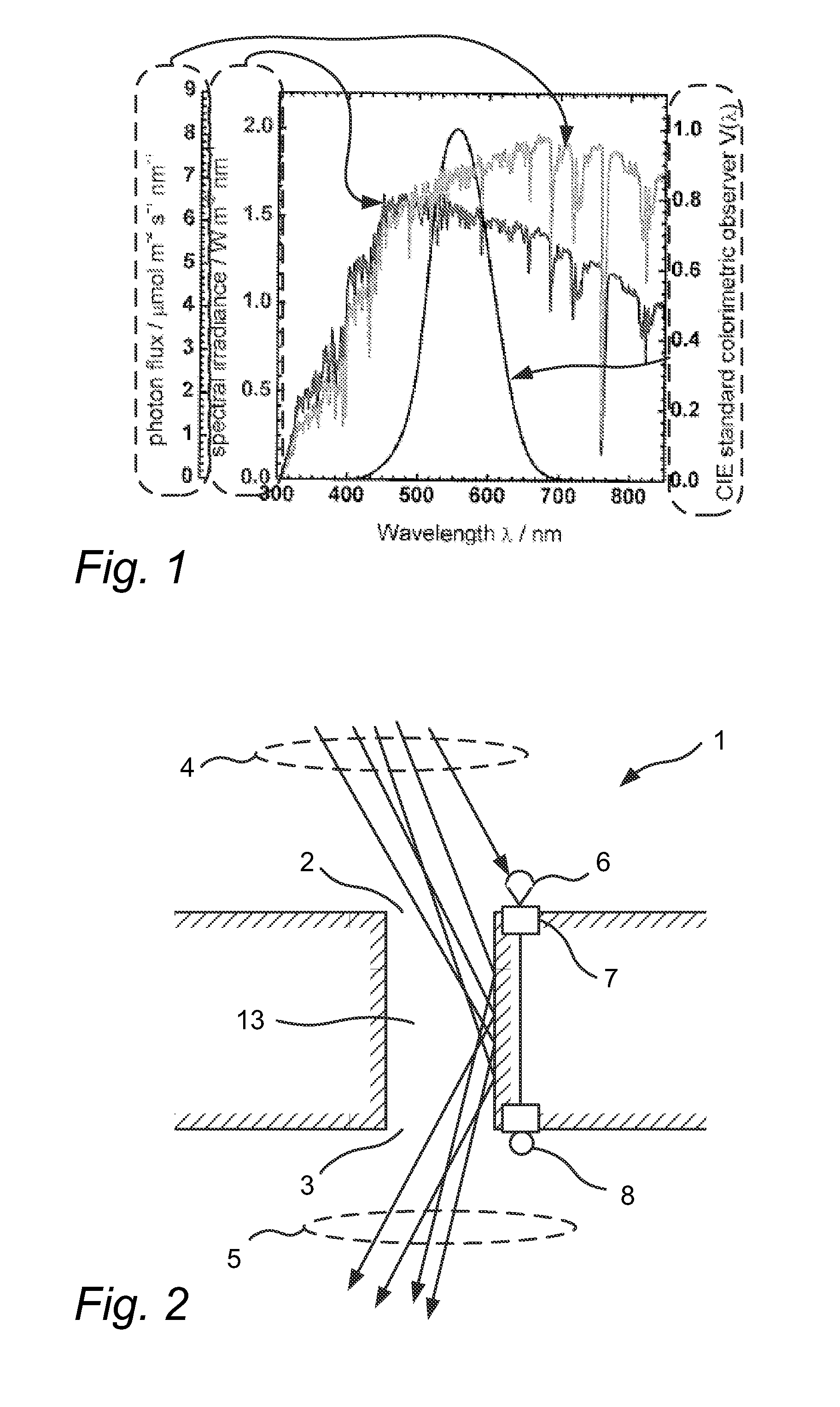
[0005]The inventors of the disclosed embodiments have identified drawbacks associated with the techniques described above. For example, in order to know how to drive and control the one or more artificial light sources in the above described hybrid arrangement it may be advantageous to know the flux and colour of the daylight that is entering the light tube. However, since the position of the sun is dependent on the day, the time of year and the location of the light tube and the intensity and colour temperature of the sun depends on the weather conditions and the orientation of the light tube with respect to its surroundings, it may be advantageous to sense the attributes of the daylight. This is however not trivial due to the variability of the daylight. Further, because the entry angle of direct sunlight is continually changing it is not easy to find the right position and method to accurately measure the sunlight parameters.
[0006]It is therefore an object of the present invention to overcome these problems, and to provide an improved lighting system that provides light in an efficient way with low losses. Particularly, the inventors of the disclosed embodiments have discovered that placing the light sensor at the light inlet of the arrangement surprisingly improves the performance.
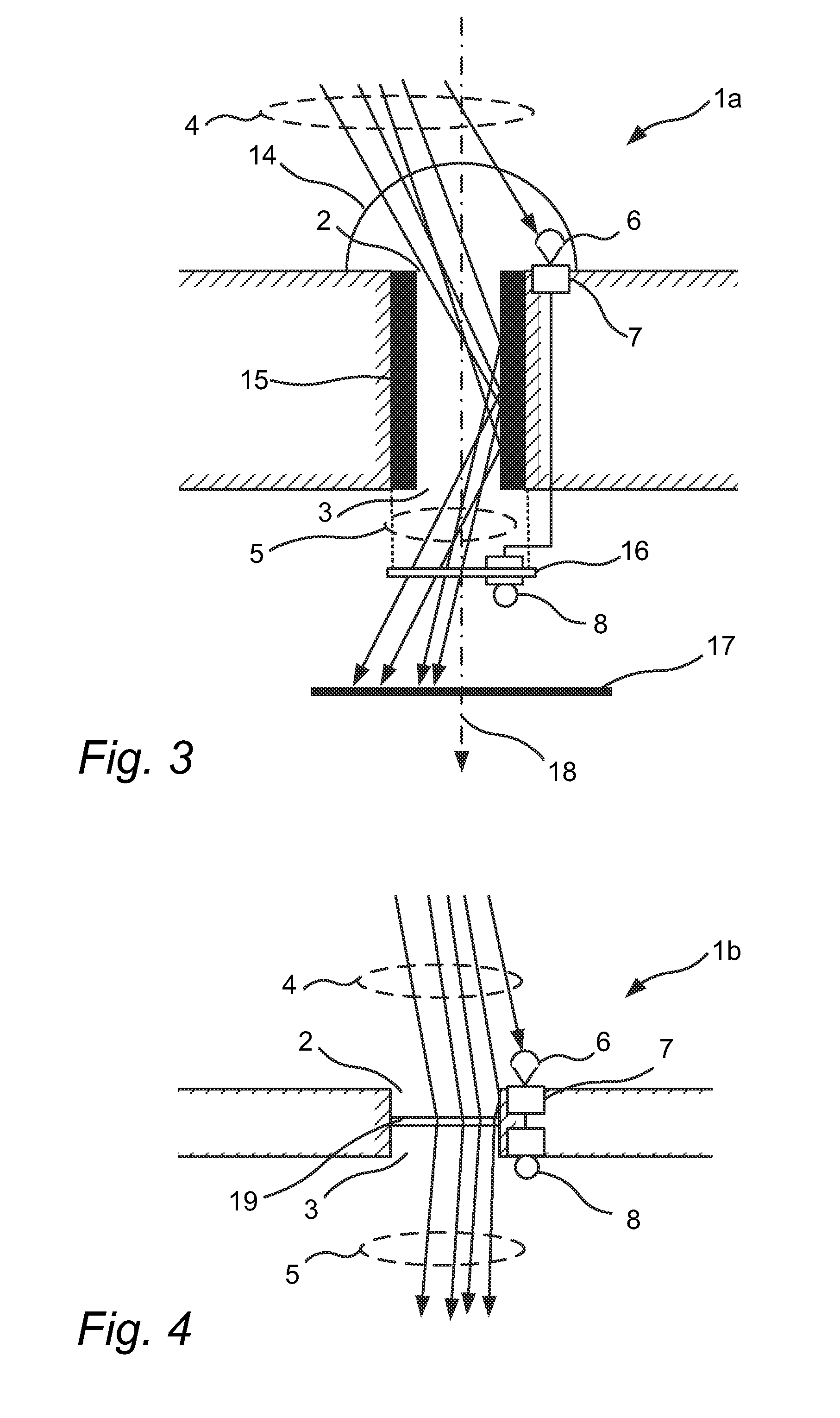
[0009]Advantageously, the disclosed daylight harvesting system thereby comprises adequate means of measuring the characteristics of the continually changing light conditions of the incident light to allow the accurate information of flux (and colour point) of the sunlight (as defined by the incident light) captured by the daylight harvesting system to be communicated to the driving controls of the artificial light sources. This enables control of the artificial light sources. This may in turn enable effective means for accurately monitoring outside light (i.e. light at the light inlet) to allow the control of light inside an interior space, such as a room (i.e. at the light outlet). There is thus recited a specific placement of the light sensor, namely that it is placed such that the incident light received by the light sensor exclusively is affected by the incident light as received by the light inlet. The photo sensor is thereby advantageously arranged only to receive and measure incident light corresponding to that entering the light inlet. In addition there is recited a specific placement of the artificial light source, namely that it is placed at the light outlet. In combination this provides efficient redistribution of the daylight within the interior space and also efficient and seamless integration of the output light with the light provided by the artificial light source. An observer located in the interior space may thereby not be able to distinguish the artificial light source's light from the light outlet's light. Furthermore, the disclosed sensor location and orientation is optimal since this connects the collected daylight flux (intensity and color point) at the light inlet with the illuminance at the light outlet in a one-to-one and nearly linear relation.
[0013]The reflective surface may be tiltedly arranged in relation to a substantially horizontal plane so as to increase the degree of illumination. This may increase the accuracy of the measurement.

Problems solved by technology

Further, because the entry angle of direct sunlight is continually changing it is not easy to find the right position and method to accurately measure the sunlight parameters.

Method used


Image

  • Daylight sensing arrangement for a hybrid luminaire
  • Daylight sensing arrangement for a hybrid luminaire
  • Daylight sensing arrangement for a hybrid luminaire

Examples


Embodiment Construction

[0031]The present invention will now be described more fully hereinafter with reference to the accompanying drawings, in which currently preferred embodiments of the invention are shown. This invention may, however, be embodied in many different forms and should not be construed as limited to the embodiments set forth herein; rather, these embodiments are provided for thoroughness and completeness, and fully convey the scope of the invention to the skilled addressee. Like reference characters refer to like elements throughout.

[0032]The terms “upstream” and “downstream” as used herein relate to an arrangement of items or features relative to the propagation of light from a light source. Relative to a first position within a beam of light from the light source, a second position in the beam of light closer to the light source is “upstream”, and a third position within the beam of light further away from the light source is “downstream”.

[0033]The term “light axis” as used herein relate...


PUM


Abstract

The disclosed embodiments relate to a daylight harvesting system (1). The daylight harvesting system comprises a light distribution device comprising a light inlet (2) for receiving incident light (3), and a light outlet (4) for providing output light (5) received by the light inlet into an interior space. A light sensor (6) is arranged to receive and measure a light level of the incident light and to provide a measurement signal representative thereof. Control circuitry (7) is arranged to receive the measurement signal, and to provide a control signal based on the measurement signal to an artificial light source (8) placed at the light outlet. The light sensor is placed relative the light inlet such that the incident light received by the light sensor exclusively is affected by the incident light as received by the light inlet.

Description

FIELD OF THE INVENTION[0001]The present invention relates in general to a lighting system and in particular to an arrangement for transporting light from a light inlet to a light outlet in such a system.BACKGROUND OF THE INVENTION[0002]There is a lot of daylight available during the day which currently is hardly used in windowless spaces. In professional buildings in areas like washrooms, halls and stairs often artificial light is constantly burning during working hours.[0003]Additionally it is often desired by people to have natural light wherever possible. Also, having more natural light available inter alia in hospitals is known to be welcomed by personnel as well as patients.[0004]Several options are known where daylight is put to more effective use, such as light tubes used for transporting daylight into a building. The light tube typically has an inlet for receiving daylight at the roof of a building. The received daylight is transmitted through a pipe of the light tube to an ...

Claims


Application Information

Patent Timeline
Patent Type & Authority Patents(United States)
IPC IPC(8): F21S19/00H05B37/02
CPCH05B37/0218F21S19/005Y02B20/46H05B47/11Y02B20/40
Inventor GOMMANS, HENDRIKUS HUBERTUS PETRUSMEIJER, EDUARD JOHANNES
Owner SIGNIFY HLDG BV
Why Eureka
Try Eureka