Surgical distance adjusting assembly for a bone distractor

a technology of distancing assembly and surgical device, which is applied in the field of surgical device distancing assembly, can solve the problems of increased risk of infection, affecting the function of the surgical device, and affecting the effect of the surgical device on the patient's recovery,

Active Publication Date: 2014-06-12
STRYKER EURO OPERATIONS HLDG LLC
View PDF6 Cites 8 Cited by
  • Summary
  • Abstract
  • Description
  • Claims
  • Application Information

AI Technical Summary

Benefits of technology

The patent text is about a surgical distance adjusting assembly for a bone distractor. The assembly helps with the surgical procedure when the bone distractor needs to be explanted. The technical effect of this invention is to make the surgical procedure easier and more efficient.

Problems solved by technology

The orthopedic system has a bulky and very complicated structure which does not efficiently utilize its size.
Further, due to the complicated removal mechanism, several steps are necessary to remove the bone distractor, wherein the sleeves, the fasteners and the plates may get stuck or jammed during explantation.
The large size of the distractor and the complicated bone plate holding and removal mechanism also lead to more interference with surrounding tissue, with an increased risk of infections.

Method used


Image

  • Surgical distance adjusting assembly for a bone distractor
  • Surgical distance adjusting assembly for a bone distractor
  • Surgical distance adjusting assembly for a bone distractor

Examples


first embodiment

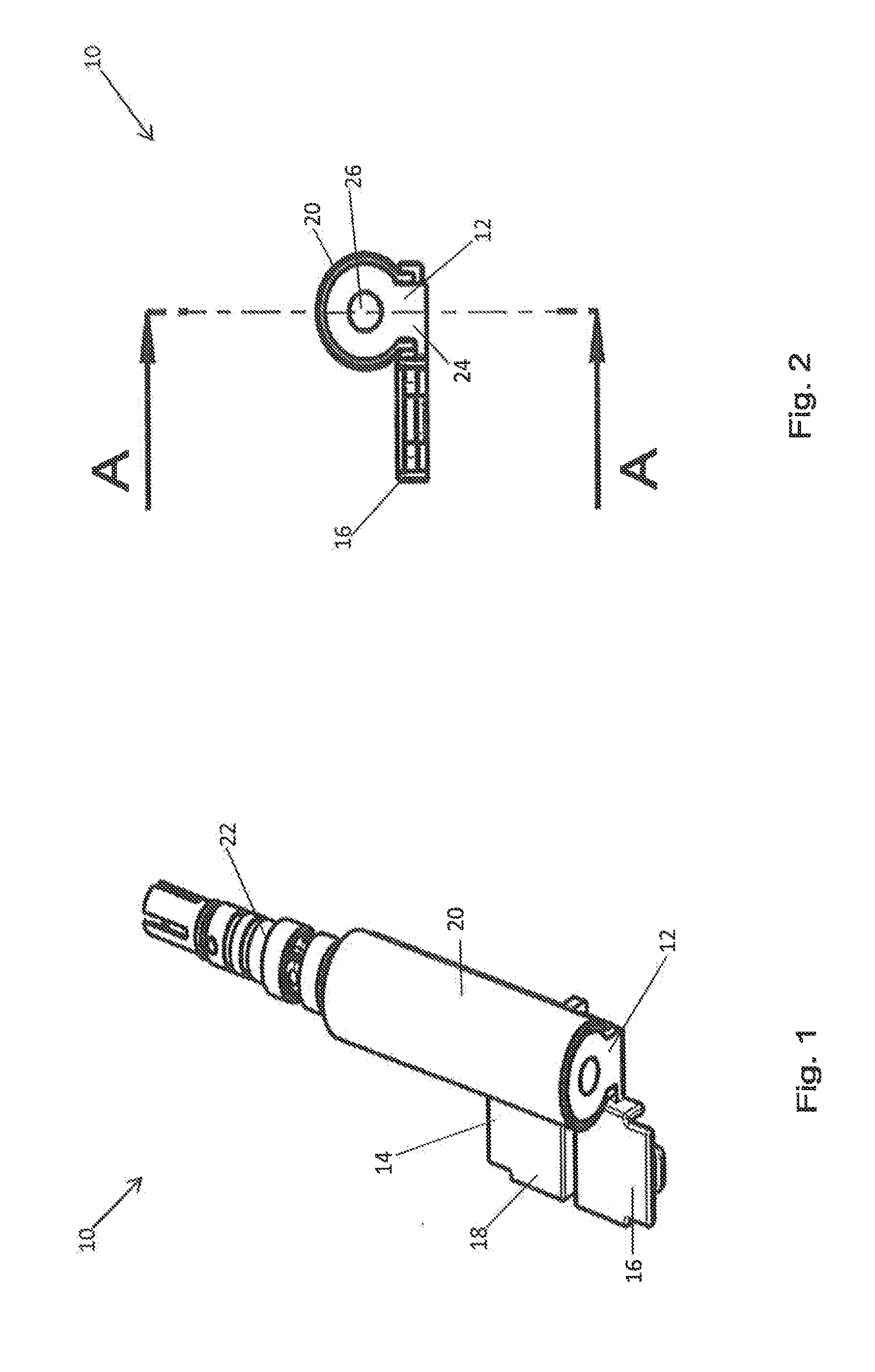
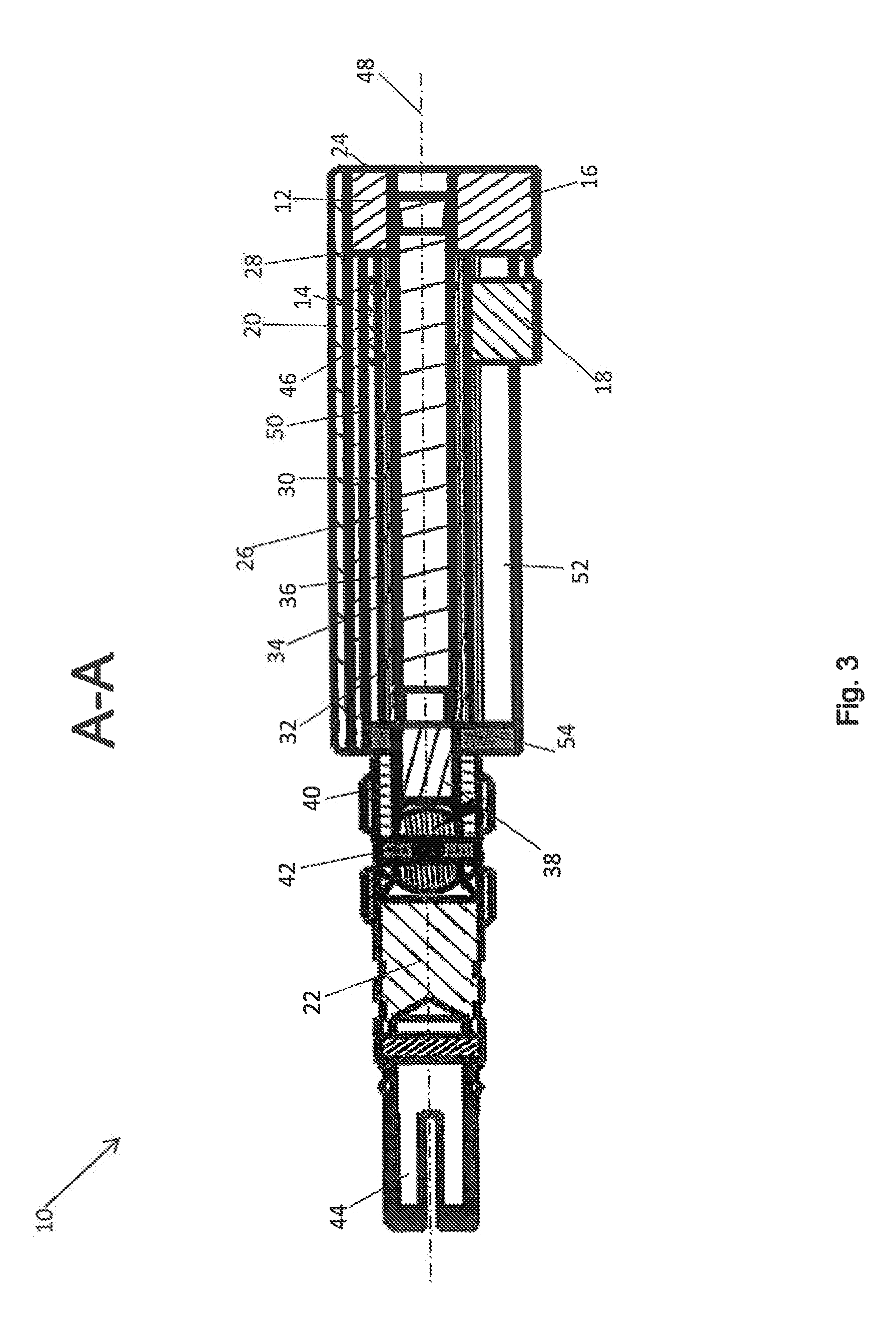
[0105]FIG. 11 shows a perspective view of the base 12 according to a The base 12 comprises a cylindrical portion 84 with a cylindrical clearance 86. The rod 26 is thus rigidly fixed to the base 12 at the center of the cylindrical portion 84 within the cylindrical clearance 86. A cuboid 88 with a rectangular base extends radially from the cylindrical portion 84 of base 12. In FIG. 11, it can be seen that the outer contour of the cylindrical portion 84 of the base 12 corresponds to the inner surface of the rod cover 20 (see FIGS. 2 and 6).

[0106]FIG. 12 shows a bottom view of the base 12 of FIG. 11. The base 12 comprises the first connecting portion 16 which substantially extends in a perpendicular direction with respect to a longitudinal axis of the cylindrical portion 84 of the base 12. Thus, the first connecting portion 16 of the base 12 substantially extends in a perpendicular direction with respect to the longitudinal axis 48 of the adjusting assembly 10 (see FIGS. 1 and 3). The ...

second embodiment

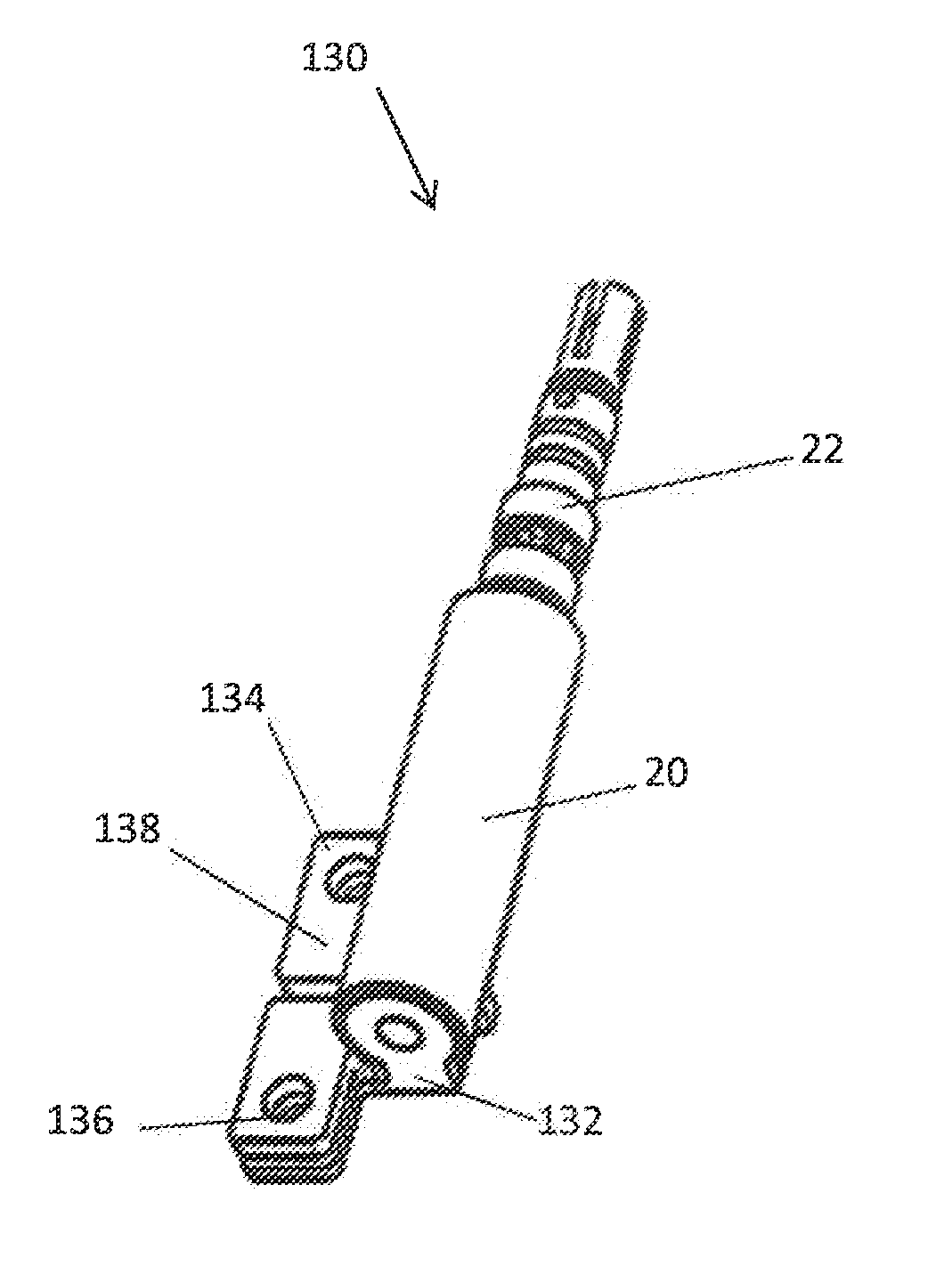
[0132]FIG. 30b shows a perspective view of a second bone attachment member 154 according to a FIG. 31b shows a top view of the second bone attachment member 154 of FIG. 30b and FIG. 32b shows a cross section of the second bone attachment member 154 along line J-J of FIG. 31b. The second bone attachment member 154 is generally configured as the first bone attachment member 148 as described above with reference to FIGS. 30a to 32a and hereinafter. The difference between the second bone attachment member 154 and the first bone attachment member 148 is that the second bone attachment member 154 has another orientation as the first bone attachment member 148. Thus, the first bone attachment member 148 is adapted to be releasably coupled to the base 132 and the second bone attachment member 154 is adapted to be releasably coupled to the carrier 134. The first and second bone attachment members 148 and 154 may be made of a bio-resorbable material. Alternatively, the first and second bone ...


PUM


Abstract

A surgical distance adjusting assembly for a distractor has a base having a first connecting portion configured to hold a first bone attachment member and a carrier having a second connecting portion configured to hold a second bone attachment member. The base and the carrier are movable relative to each other, wherein the first and second connecting portions provide a releasable mechanical coupling to the first and second bone attachment members. The releasable mechanical coupling comprises a hook member at one or both of the first and second connecting portions and configured to engage the respective bone attachment member. Alternatively, the releasable mechanical coupling comprises an opening at one or both of the first and second connecting portions. The opening has a thread for a fixation screw configured to releasable couple the respective bone attachment member to the respective connecting portion.

Description

CROSS-REFERENCE TO RELATED APPLICATIONS[0001]The present application claims priority to European Patent Application No. 12008294.6 filed Dec. 12, 2012, the disclosure of which is hereby incorporated herein by reference.BACKGROUND OF THE INVENTION[0002]The present disclosure generally relates to a surgical distance adjusting assembly for use in surgical procedures. In particular, a surgical distance adjusting assembly for a bone distractor, the bone distractor as well as a system comprising the bone distractor are described.[0003]When performing a reconstructive osteotomy or segment advancement of a cranium or jaw bone, the bone is typically separated into two or more sections. Plates of a bone distractor are then fixed to the respective bone sections by bone screws.[0004]After their fixation to bone, the plates are successively distracted. The bone distractor may be operated by rotating a wire through an incision in the skin of the patient. The successive separation of the bone sect...

Claims


Application Information

Patent Timeline
Patent Type & Authority Applications(United States)
IPC IPC(8): A61B17/66
CPCA61B17/663A61B17/666A61B17/8071A61B2017/00991A61B17/66
Inventor KNOEPFLE, CHRISTIANGREINER, KARLSCHMUCK, MANFREDVOLK, MICHAEL
Owner STRYKER EURO OPERATIONS HLDG LLC
Why Eureka
Try Eureka