Rotating mechanism and electronic device with same

Inactive Publication Date: 2014-06-19
CLOUD NETWORK TECH SINGAPORE PTE LTD
View PDF21 Cites 53 Cited by
  • Summary
  • Abstract
  • Description
  • Claims
  • Application Information

AI Technical Summary

Problems solved by technology

However, when the electronic device is used, time is required to adjust an angle between the two parts, which is inconvenient.

Method used


Image

  • Rotating mechanism and electronic device with same
  • Rotating mechanism and electronic device with same
  • Rotating mechanism and electronic device with same

Examples


Embodiment Construction

[0016]Embodiments of the present disclosure will now be described in detail below, with reference to the accompanying drawings.

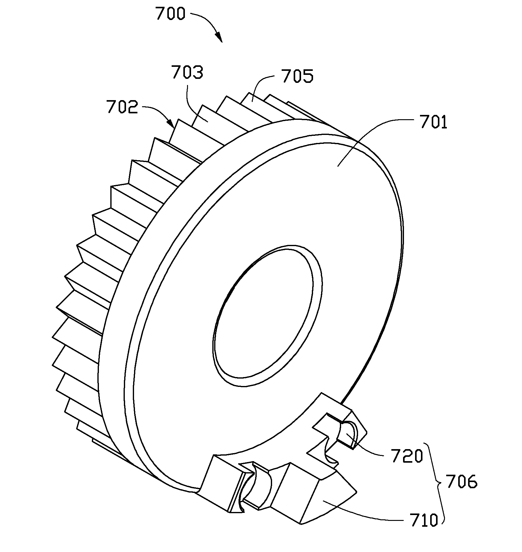
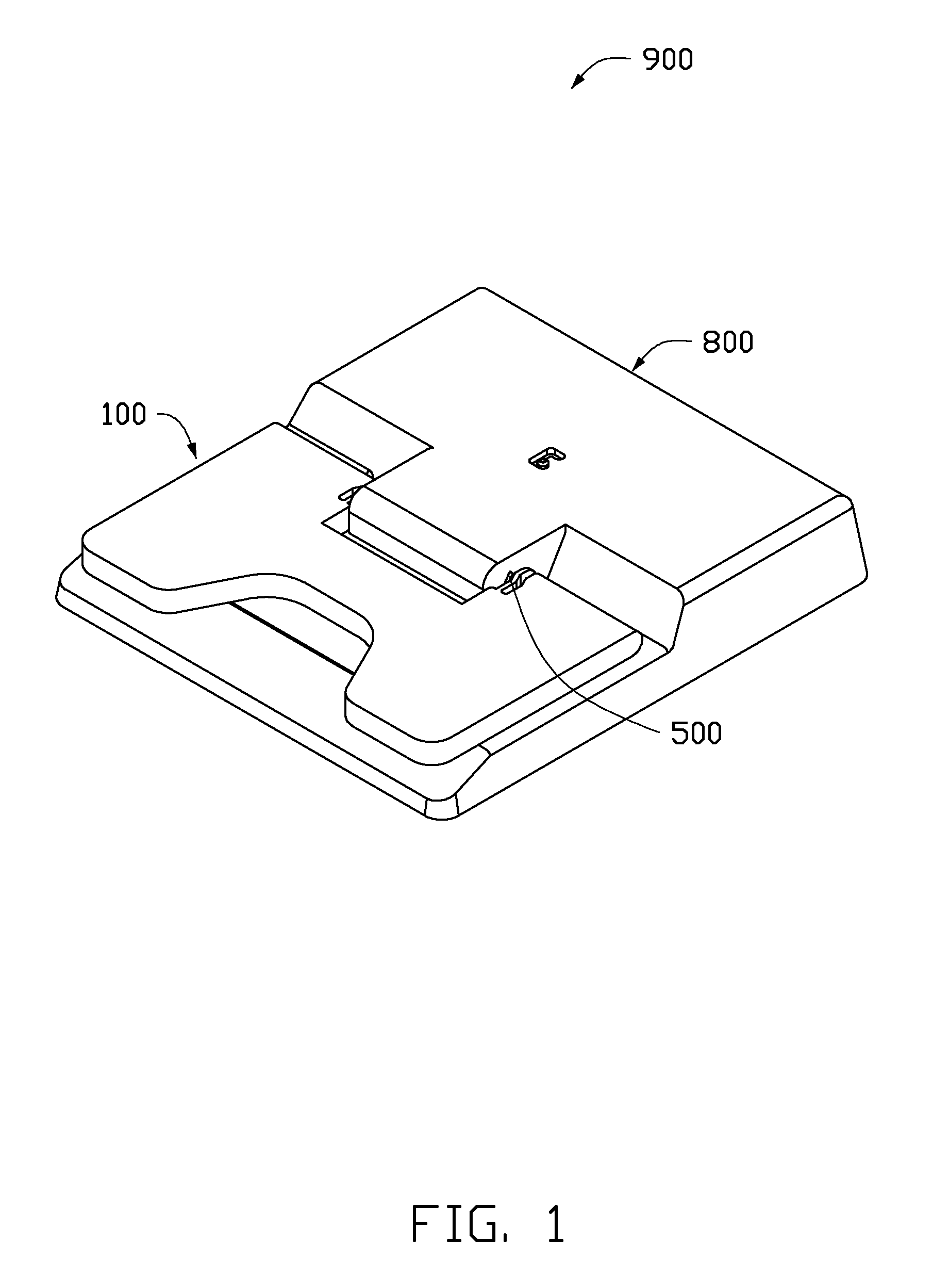
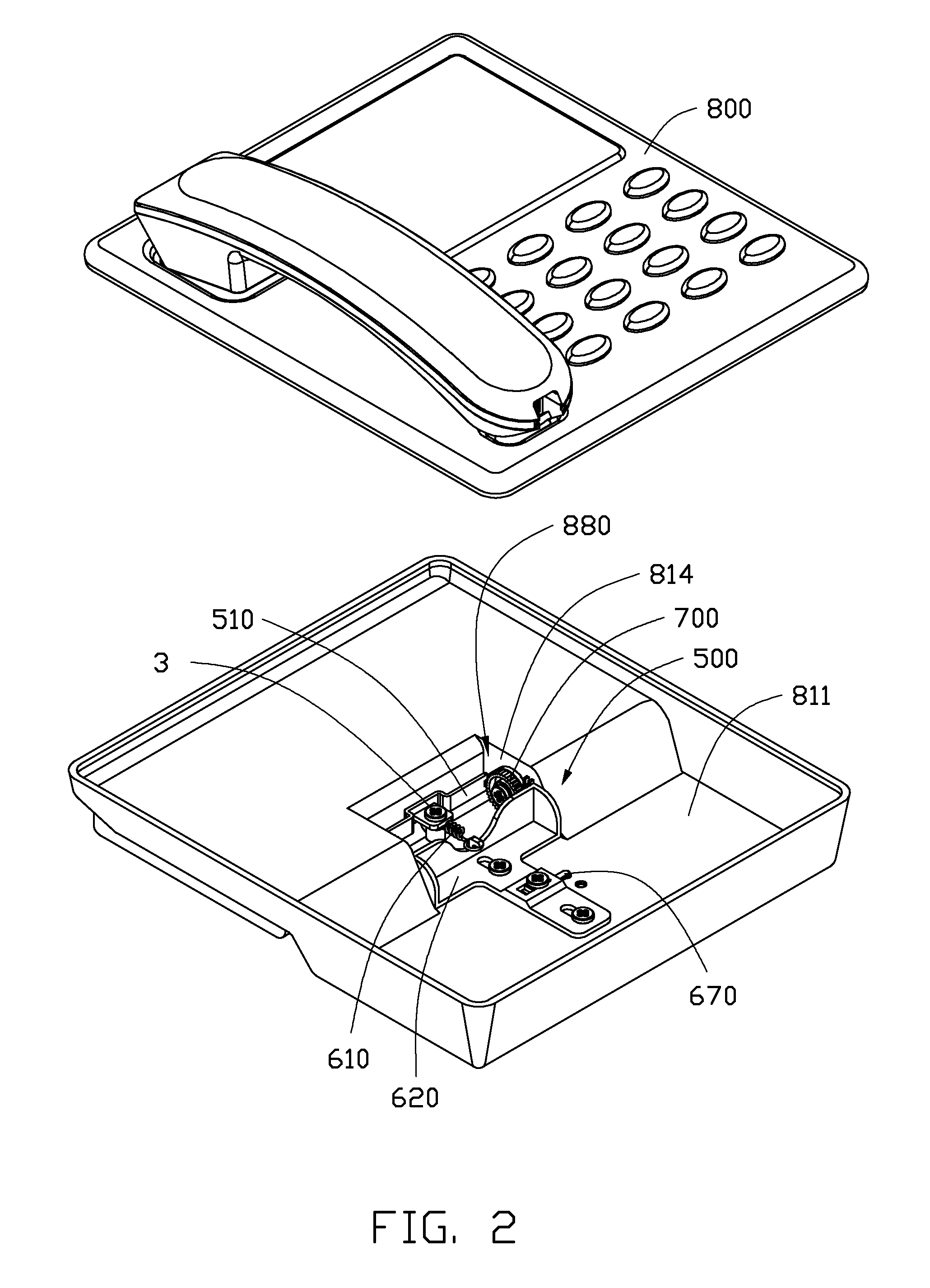
[0017]FIGS. 1 and 2 illustrate an electronic device 900 in accordance with an exemplary embodiment. The electronic device 900 includes a first body 800, a second body 100, and a rotating mechanism 500 rotatably connecting the first body 800 to the second body 100. In this embodiment, the electronic device 900 is a telephone. The first body 800 is a base with a receiver. The second body 100 is a support rotatably connected to a bottom of the base for supporting the base at a predetermined angle.

[0018]The first body 800 includes a pair of sidewalls 814 and a base board 811 perpendicularly connected to the sidewalls 814. The second body 100 is rotatably connected to the sidewalls 814. The first body 800 defines a receiving space 880 between the pair of sidewalls 814 for accommodating the rotating mechanism 500.

[0019]FIGS. 3 and 4 show that each of the sidewalls...


PUM


Abstract

An exemplary rotating mechanism for positioning a rotation angle of a second body relative to a first body is provided. The first body includes a pair of sidewalls. The second body includes a pair of connecting arms rotatably connected to the sidewalls. The rotating mechanism includes a pair of positioning gears rotatably connected to the sidewalls, a brake slidably connected to the first body, and a button fastened to the brake. Each of the positioning gears includes a positioning block extending out of the sidewalls. The brake is driven to brake the positioning gears by the button when the button is moved towards the sidewalls. The positioning block is fixed at a predetermined position to position the rotation angle of the second body when the positioning gears are braked.

Description

BACKGROUND[0001]1. Technical Field[0002]The present disclosure relates to rotating mechanisms for rotatably connecting different bodies, and more particularly, to a rotating mechanism capable of adjusting a relative rotation angle between the different bodies.[0003]2. Description of Related Art[0004]An electronic device, such as a cellular phone or a notebook computer, can include two parts rotatably connected to each other. However, when the electronic device is used, time is required to adjust an angle between the two parts, which is inconvenient.[0005]Therefore, it is desirable to provide a means which can overcome the above-mentioned problems.BRIEF DESCRIPTION OF THE DRAWINGS[0006]Many aspects of the embodiments can be better understood with references to the following drawings. The components in the drawings are not necessarily drawn to scale, the emphasis instead being placed upon clearly illustrating the principles of the embodiments. Moreover, in the drawings, like reference...

Claims


Application Information

Patent Timeline
Patent Type & Authority Applications(United States)
IPC IPC(8): H05K5/02E05D11/10E05D7/00
CPCG06F1/1681E05D7/0045
Inventor KUAN, CHANG-MINGCHIU, MING-CHIEN
Owner CLOUD NETWORK TECH SINGAPORE PTE LTD
Why Eureka
Try Eureka