Plating Stub Resonance Shift with Filter Stub Design Methodology

a technology of filter stubs and design methodologies, applied in waveguides, basic electric elements, waveguide type devices, etc., can solve the problems of increasing signal loss at low frequencies, undesirable plating stubs in the wire bond package, and limited frequency bandwidth of the serialization-deserialization application of high-speed serialization-deserialization (serdes) application

Inactive Publication Date: 2014-06-19
GLOBALFOUNDRIES INC
View PDF7 Cites 4 Cited by
  • Summary
  • Abstract
  • Description
  • Claims
  • Application Information

AI Technical Summary

Benefits of technology

[0009]According to one embodiment of the present invention, a technique is provided to increase signal bandwidth of data processing signals by providing a plating stub as a filter using multiple line segments of different widths to filter the reflected high frequency components bouncing from the stub end toward the signal path. This stub-filter shifts the resonance point to a much higher frequency, placing that point of resonance beyond the bandwidth of interest without sacrificing a low frequency loss. Accordingly, there is provided an apparatus comprising a stub filter of a substrate, comprising a multi-segmented stub comprising a plurality of stub portions, where one of the stub portions has a different impedance than another of the stub portions.

Problems solved by technology

For example, wire bond packages are limited in frequency bandwidth for a high speed serialization-deserialization (SerDes) application due in part to the detrimental effect of a quarter wave-length resonance effect of the plating stubs.
The undesirable plating stub in the wire bond package is a by-product of the manufacturing process which requires plating of the electrodes.
Both of these terminator methods increase signal losses at low frequencies—where a majority of digital signal energy resides—as part of signal energy is tunneled to ground through the stub and the terminating resistor and hence is wasted while preventing high frequency notch at quarter-wave length resonance.

Method used


Image

  • Plating Stub Resonance Shift with Filter Stub Design Methodology
  • Plating Stub Resonance Shift with Filter Stub Design Methodology
  • Plating Stub Resonance Shift with Filter Stub Design Methodology

Examples


Embodiment Construction

[0018]As will be appreciated by one skilled in the art, aspects of the present invention may be embodied as a system or method. Accordingly, aspects of the present invention may take the form of an entirely hardware embodiment, an entirely software embodiment (including firmware, resident software, micro-code, etc.) or an embodiment combining software and hardware aspects that may all generally be referred to herein as a “circuit,”“module” or “system.” Aspects of the present invention are described below with reference to flowchart illustrations and / or block diagrams of methods and apparatus (systems) according to embodiments of the invention.

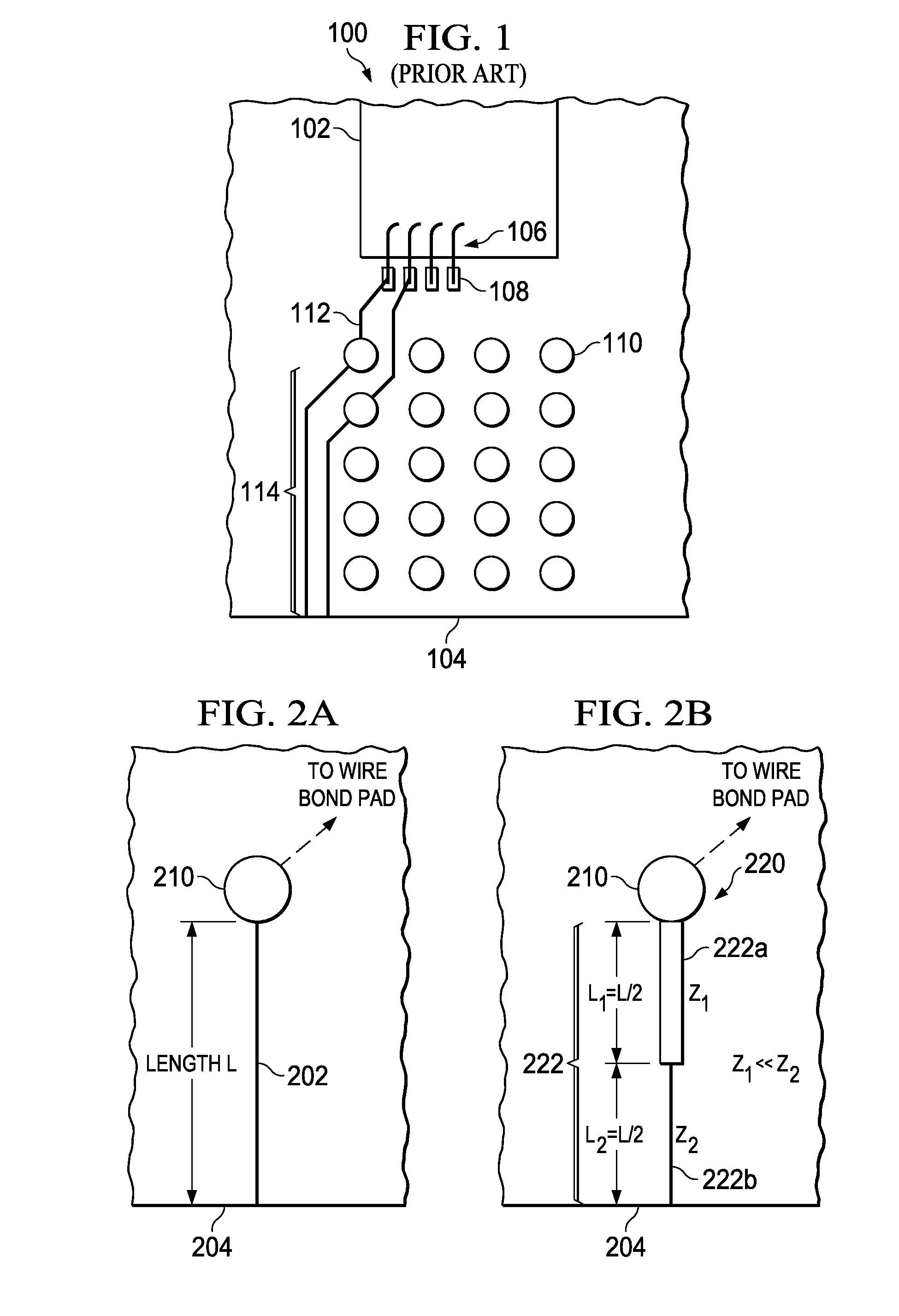
[0019]Turning now to FIG. 2A, there is depicted at 202 an example stub of a current chip carrier. This stub 202, which is the result of a manufacturing process where this signal line further extends to another portion of the substrate (not shown) that has been cut-away since it is no longer needed after testing the electronic package prior to c...


PUM


Abstract

A technique is provided to increase signal bandwidth of data processing signals by providing a plating stub as a filter using multiple line segments of different widths to filter the reflected high frequency components bouncing from the stub end toward the signal path. This stub-filter shifts the resonance point to a much higher frequency, placing that point of resonance beyond the bandwidth of interest without sacrificing a low frequency loss. Accordingly, there is provided an apparatus comprising a stub filter of a substrate, comprising a multi-segmented stub comprising a plurality of stub portions, where one of the stub portions has a different impedance than another of the stub portions.

Description

[0001]This application is a continuation of U.S. patent application Ser. No. 13 / 491,873 filed on Jun. 8, 2012.[0002]1. Field[0003]The disclosure relates generally to apparatus and techniques for mitigating signal reflections for signals in a data processing system, and more specifically relates to techniques for mitigating adverse signal reflections caused by unwanted plating stubs in an electronic package.[0004]2. Description of the Related Art[0005]In a data processing system, as processor speeds increase there is a growing need to make improvements in electronic packaging of electrical and electronic components such that the packages themselves do not adversely influence electrical signals passing from one electrical / electronic component to another that may be housed in different packages.[0006]For example, wire bond packages are limited in frequency bandwidth for a high speed serialization-deserialization (SerDes) application due in part to the detrimental effect of a quarter wa...

Claims


Application Information

Patent Timeline
Patent Type & Authority Applications(United States)
IPC IPC(8): H01P1/203
CPCH01P1/203H01P1/2039
Inventor NA, NANJUPHAM, NAM H.WALLS, LLOYD A.
Owner GLOBALFOUNDRIES INC
Why Eureka
Try Eureka