
Electrical connector assembled component

Active Publication Date: 2014-06-19
HIROSE ELECTRIC GROUP
View PDF0 Cites 13 Cited by
  • Summary
  • Abstract
  • Description
  • Claims
  • Application Information

AI Technical Summary

Benefits of technology

The present invention relates to an intermediate connector that has conducting terminals with improved flexing elasticity, and a housing with easy mounting of conducting terminals. The connector can have two holding members that hold the conducting terminals while providing them with freedom of movement relative to each other. The conducting terminals can also be supported by spring members, within the elastically displaceable range, to secure the floating ability. Moreover, the invention provides mating connectors with sufficient floating and contact pressure between terminals, regardless of their angular positions, which ensures reliable connection characteristics.

Problems solved by technology

Furthermore, according to the intermediate connector of the conventional connector assembled component disclosed in Patent Reference, connection can be made only in a way such that the fitting directions of two mating connectors are aligned in one direction, and such intermediate connector is not suitable for connection when the circuit boards, to which the respective mating connectors are attached, are perpendicular to each other.
Second, since the spring piece is bent only in the thickness direction, the throat-shaped contact site to the fixed contact forms a straight line, and the length of the line is the maximum at one side of the quadrangle od the fixed contact that has a quadrangle section, so that the length of the contact cannot be considered sufficient and the contact area is extremely small.
Fifth, the intermediate connector cannot be fitted and connected to the both mating connectors in one straight line direction, so that it is impossible to apply in so-called right-angle connection, in which circuit boards of the two mating connectors are disposed at a right angle from each other.

Method used


Image

  • Electrical connector assembled component
  • Electrical connector assembled component
  • Electrical connector assembled component

Examples


Embodiment Construction

[0041]Hereunder, embodiments of the present invention will be described with reference to the accompanying drawings.

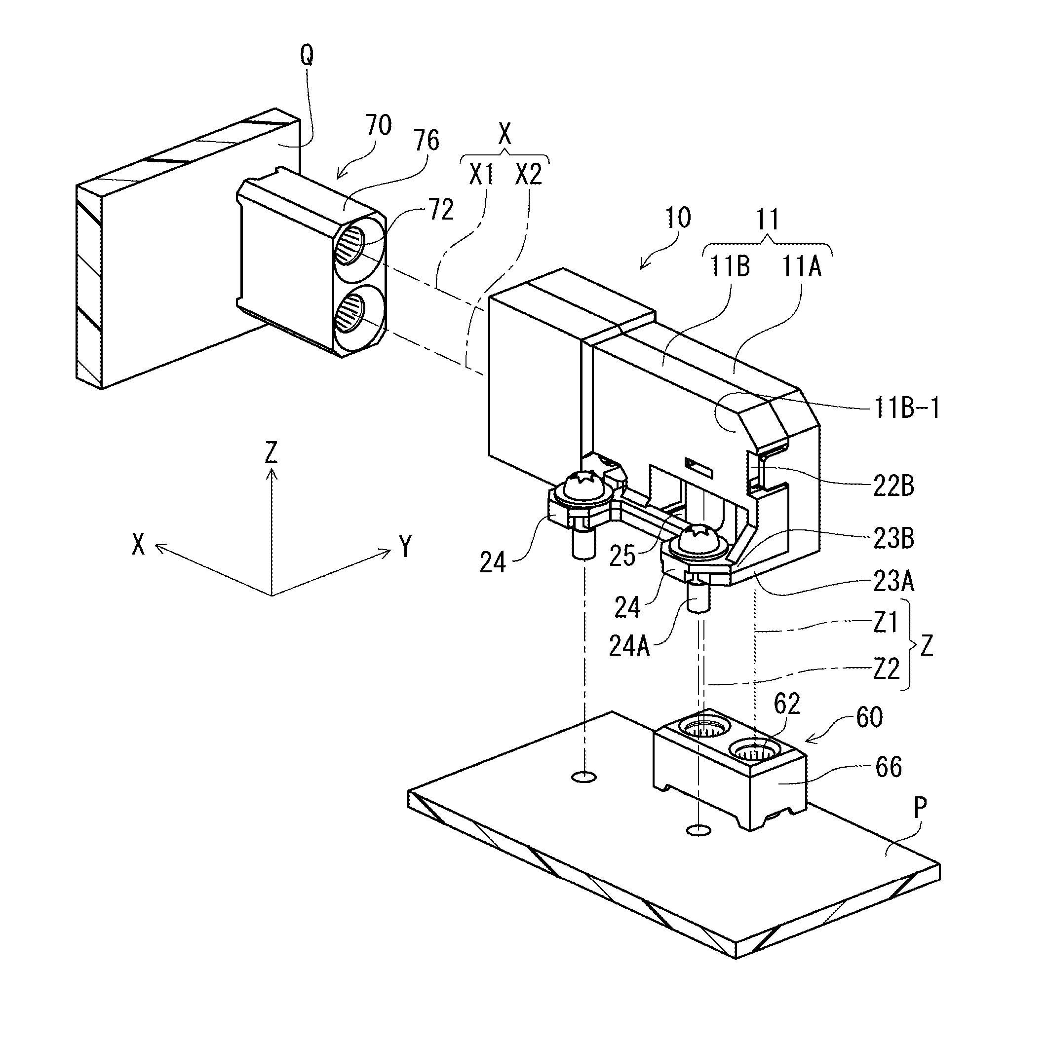
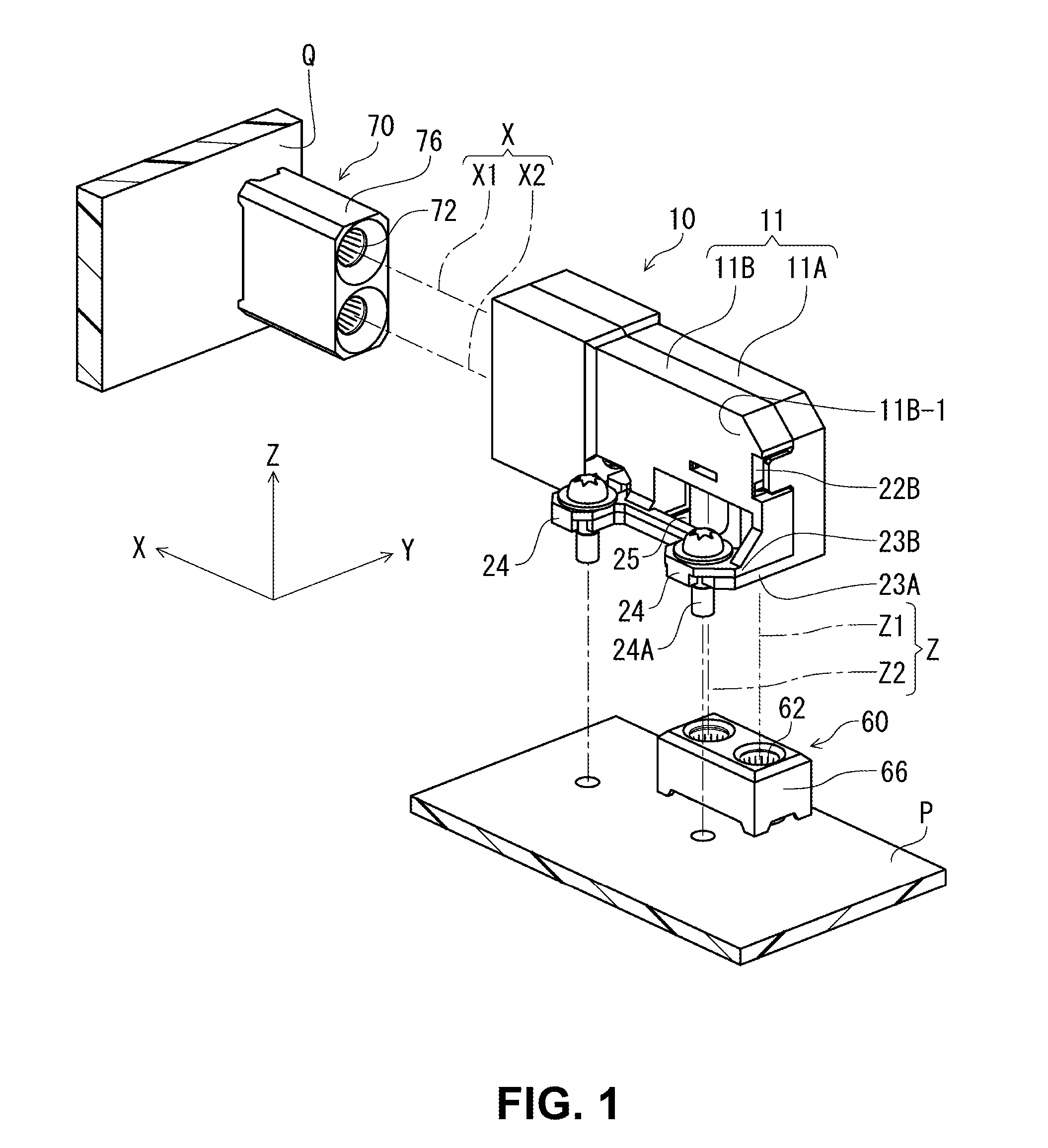
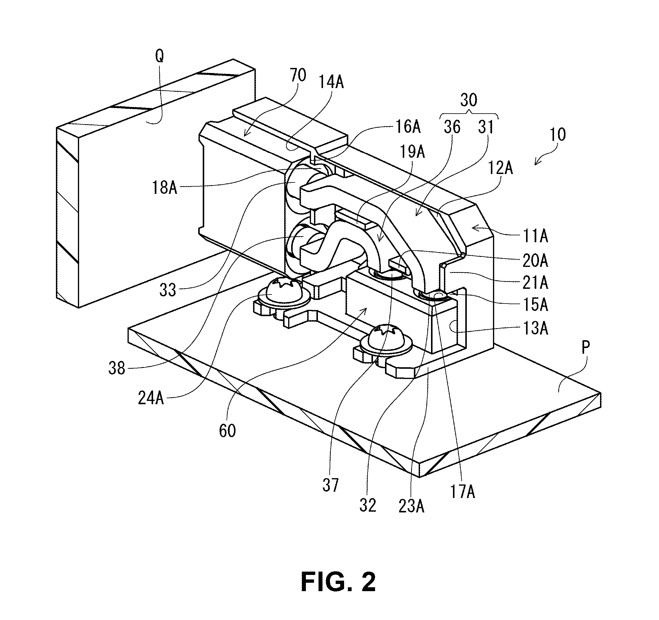
[0042]FIG. 1 is a perspective view of an electrical connector assembled component of the present invention, which is composed of a first attachment connector and a second attachment connector that are connected via an intermediate connector, in state before connecting the respective connectors. FIG. 2 is a perspective view showing the state after the connection, with only one housing half of the intermediate connector is attached thereto and the other housing half is detached therefrom.

[0043]As shown in FIG. 1, the first attachment connector 60 for connecting to the intermediate connector 10 is attached to a circuit board P that is provided as a circuit member, and the second attachment connector 70 is attached to a circuit board Q that is provided as a circuit member, respectively. The first and the second attachment connectors 60 and 70 are respectively fitted to the...


PUM


Abstract

An electrical connector assembled component includes a first attachment connector for attaching to a first circuit board member; a second attachment connector for attaching to a second circuit member; and an intermediate connector that is provided between the first attachment connector and the second attachment connector. The intermediate connector has conducting terminals in the housing. The first attachment connector and the second attachment connector have first receiving terminals and second receiving terminals. Each conducting terminal has a first contact section; a second contact section; and a joining section. An elastic cylindrical member is made of metal and can elastically deform in the radial direction so as to allow movement of the first contact section and the second contact section. The elastic cylindrical member contacts with the first contact section and the first receiving terminal or the second contact section and the second receiving terminal.

Description

BACKGROUND OF THE INVENTION AND RELATED ART STATEMENT[0001]The present invention relates to an electrical connector assembled component. More specifically, the present invention relates to an electrical connector assembled component having conducting terminals.[0002]As an electrical connector assembled component of this type, there has been known a conventional electrical connector assembled component disclosed in Patent Reference.[0003]Patent Reference: Japanese Patent Application Publication No. 2011-060732[0004]According to Patent Reference, the conventional connector assembled component includes an intermediate connector, which connects a mating connector mounted on one circuit board and another mating connector mounted on the other circuit board. In the conventional connector assembled component disclosed in Patent Reference, the intermediate connector connects the mating connectors, with the one and the other circuit boards are parallel to each other. Therefore, the two connec...

Claims


Application Information

Patent Timeline
IPC IPC(8): H01R12/72
CPCH01R12/72H01R12/7082H01R12/737H01R13/187H01R13/424H01R13/625H01R13/627
Inventor KIKUCHI, TAKASHIMATSUZAWA, ATSUSHI
Owner HIROSE ELECTRIC GROUP
Learn More