
Excavating tooth wear indicator and method

a technology of wear indicators and excavating teeth, which is applied in the field of excavating teeth, can solve the problems of affecting the quality of excavating teeth,

Inactive Publication Date: 2014-06-26
VOLVO CONSTR EQUIP
View PDF16 Cites 61 Cited by
  • Summary
  • Abstract
  • Description
  • Claims
  • Application Information

AI Technical Summary

Benefits of technology

The present invention provides an excavating tooth for construction machinery that includes a wear indicator for indicating when the tooth is worn out. The wear indicator is located within the tooth and is made of a flowable material that can be abrasively weared down as the tooth is worn down. The wear indicator can be a color that contrasts with the color of the working end of the tooth, and it is plugged to prevent it from flowing into the mountable end. The tooth can be easily replaced after the wear indicator becomes visible. The technical effect of the invention is to provide an improved means for replacing excavating teeth on construction machinery.

Problems solved by technology

During use, the excavating teeth are subjected to abrasive wear, which requires that the excavating teeth be replaced from time to time.
Failure to timely replace the excavating teeth may result in damage to the adaptors, which are generally more expensive to replace than just the excavating teeth.
While the timely replacement of the excavating teeth is important, replacing the excavating teeth too early may entail using less than the full useful life, which also increases costs.
While the wear indicating ribs provide an indication of wear, this system is not easily adaptable to existing machines since it requires special adaptors that include the wear indicating ribs.
This solution also requires that the excavating teeth have a large void in the region that extends around the wear indicating ribs, which, in turn, weakens the teeth at a critical area that is subjected to relatively large loads.
Moreover, this solution risks exposing the adaptors to unnecessary wear since the wear indicating ribs are on the adaptor itself and must be exposed, and thus subject to the possibility of wear, before any sort of visual indication can occur.
Additionally, as the teeth “hole out” to expose the wear indicating ribs, debris may pack the holes, thus obscuring the wear indicating ribs and possibly damaging the adaptors.
The system is designed to allow each excavating tooth to “hole out” without damaging the load bearing area of the adaptors; however, as the teeth “hole out”, debris may pack the holes, thus obscuring the appearance of the holes and possibly damaging the adaptors.
This solution also requires that the excavating teeth define a large void in the region that extends around the adaptor, which, in turn, weakens the teeth at a critical area that is subjected to relatively large loads.

Method used


Image

  • Excavating tooth wear indicator and method
  • Excavating tooth wear indicator and method
  • Excavating tooth wear indicator and method

Examples


Embodiment Construction

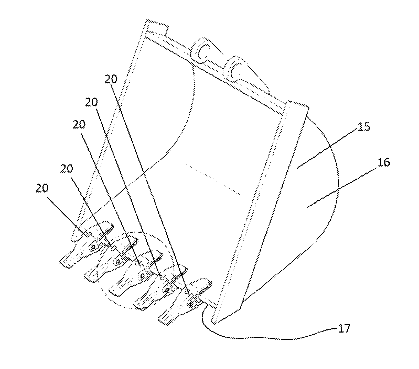
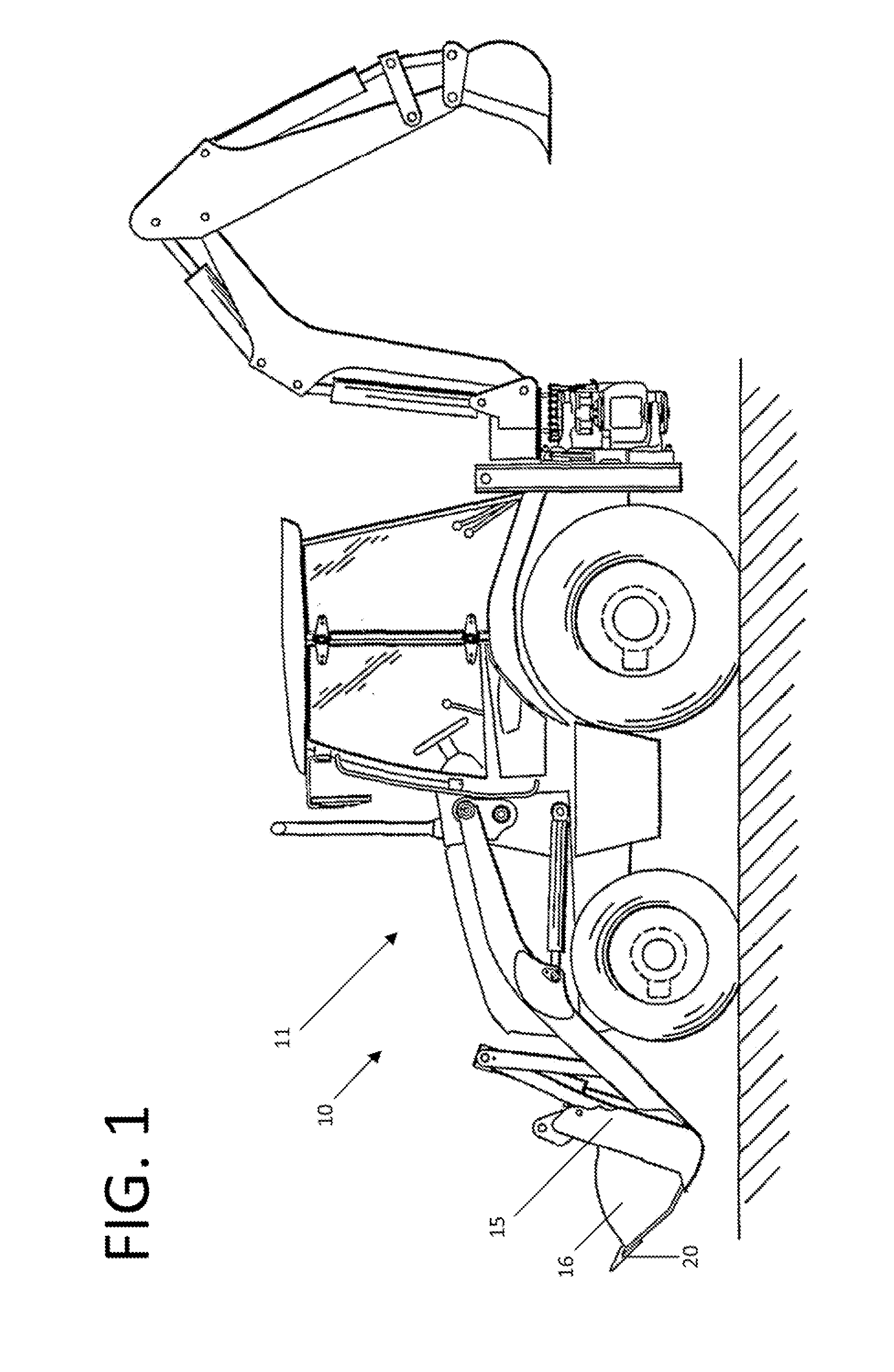
[0051]FIG. 1 depicts a construction work machine 10 according to one embodiment of the present invention. As shown therein, the construction work machine 10 may be a loader 11. Also shown, the construction work machine 10 is provided with at least one work tool 15, which in the present embodiment is shown as a bucket 16 for excavating and / or moving a material, such as, for example, gravel or earth.

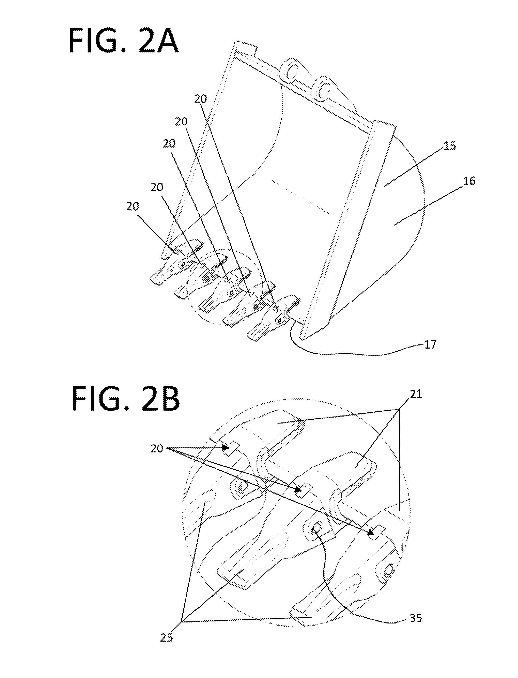
[0052]As shown in FIGS. 1-2B, the work tool 15 is provided with at least one excavating tooth assembly and preferably a plurality of excavating tooth assemblies, as at 20. As FIG. 2 best illustrates, the excavating tooth assemblies 20 are each provided with an adaptor 21 and an excavating tooth 25. According to one aspect of the present embodiment, the adaptor 21 functions as an interface that releasably secures the excavating tooth 25 to the work tool 15.

[0053]As shown in FIG. 2, the adaptor 21 may be secured to the forward lower lip 17 of the work tool 15. Those of ordinary skill in the ...


PUM

PropertyMeasurementUnit
lengthaaaaaaaaaa
coloraaaaaaaaaa
abrasive wearaaaaaaaaaa

Abstract

The present invention relates to an excavating tooth for construction machinery and a method for replacing an excavating tooth of construction machinery. The excavating tooth is provided with a working end and a mountable end. The mountable end defines a means for receiving an adaptor mounted on a work tool. The working end defines a bore. A wear indicator is located within the bore and provided with a length that is less than an unworn length of the working end and a color that visibly contrasts with a color of the working end. As the excavating tooth is worn down during use, the wear indicator becomes visible to provide a visual indication of the need to replace the excavating tooth.

Description

FIELD OF THE INVENTION[0001]The present invention relates to a wear indicator system for excavating teeth on construction machinery.BACKGROUND OF THE INVENTION[0002]Construction machinery, including, for example, skid steers, excavators, dozers, and loaders, may be provided with a work tool in the form of a bucket or blade. Often times the leading edge of such a bucket or blade is outfitted with a plurality of excavating teeth. For purposes of securing the excavating teeth to the bucket or blade, the excavating teeth typically mate with an adaptor provided on the bucket or blade. By way of example, a forward lower lip on a bucket may be provided with a series of adaptors and excavating teeth that extend along the length of the lip.[0003]During use, the excavating teeth are subjected to abrasive wear, which requires that the excavating teeth be replaced from time to time. Failure to timely replace the excavating teeth may result in damage to the adaptors, which are generally more exp...

Claims


Application Information

Patent Timeline
Patent Type & Authority Applications(United States)
IPC IPC(8): E02F9/28B23P6/00
CPCE02F9/26B23P6/00E02F9/2808E02F9/2883E02F9/2825E02F9/267Y10T29/4973
Inventor OK, SUKSANLUFT, KEVIN F.
Owner VOLVO CONSTR EQUIP
Learn More