Fasteners, Deployment Systems, and Methods for Ophthalmic Tissue Closure and Fixation of Ophthalmic Prostheses and Other Uses

a technology of ophthalmic prostheses and ophthalmic tissue, applied in the field of medical devices, systems and methods, can solve the problems of difficult tissue suturing, high cost, and high labor intensity of surgeons, and achieve the effect of reducing labor intensity and time-consuming the suturing process

Inactive Publication Date: 2014-06-26
O3 OPTIX LLC
View PDF3 Cites 22 Cited by
  • Summary
  • Abstract
  • Description
  • Claims
  • Application Information

AI Technical Summary

Benefits of technology

[0008]A variety of additional mechanisms may be employed in some embodiments. For example, in some embodiments the legs may angle toward or away from each other as they advance along straight or curving insertion paths, and plastic, elastic, and / or super-elastic deformation of the base can help bring wound edges of the tissue into engagement, advance the legs within the tissue and / or maintain the base of the fastener along the tissue surface.
[0042]With the known limitations of existing suturing and adhesive tissue closure technology and methods, there exists a need for an alternative. According to various embodiments, an apparatus and method provides an ophthalmic surgeon the versatility of mechanical closure expected of suture along with the efficiency expected with adhesive. This versatility is achieved while also providing the surgeon a more predictable closure according to various embodiments. Because of the patient's eye positioning, closure and / or fixation may be enabled by providing the ability to both grasp and clip the associated ocular tissue. The ability to also grasp enables the surgeon to a) position the necessary tissue or ocular prosthetic prior to fixation and b) create a manual “one handed” closure method as opposed to two hands required for suturing (i.e., gasper in one, needle in second). Because the duration of the fixation clip can be permanent or temporary, matching the color of the clip with the surrounding tissue would allow for surface exposed clips to be relatively hidden during the healing process, at which point the clip could remain, be removed, or absorb. To address a greater range of ocular tissues and prosthetics, some embodiments of the apparatus may be angled in such a way to provide access to areas where anatomical shallow angles exist.

Problems solved by technology

Many or all of these subspecialities may also involve prosthesis fixation, with these procedures often requiring substantial and / or difficult suturing of tissue.
Other ophthalmic therapies may involve other tissues, and a range of therapies directed throughout the body are dependent on suturing to produce the desired results, with that suturing often presenting significant challenges.
Depending on the procedure, the suturing process can be very time consuming relative to the total length of a procedure.
Additionally, the overhead expense of the surgical facility (which can be incurred not only during the underlying therapeutic procedure but also throughout the time dedicated to suturing of the access site and the like) will often result in a negative cash flow for a particularly complex suture case.
However, adhesives have been associated with disadvantages for both the surgeon and patient.
For the surgeon, adhesives can be time consuming to mix, variable in curing time, limited to linear low-force incisions, and / or less customizable than would be ideal, potentially leading to difficulty in obtaining a desired closure pressure.
For the patient, the use of adhesive for ophthalmological procedures can result in discomfort, because the typical curing process may leave a slight amount of cured adhesive standing or protruding above the intended anatomy.
The resulting height can cause significant ocular discomfort.

Method used


Image

  • Fasteners, Deployment Systems, and Methods for Ophthalmic Tissue Closure and Fixation of Ophthalmic Prostheses and Other Uses
  • Fasteners, Deployment Systems, and Methods for Ophthalmic Tissue Closure and Fixation of Ophthalmic Prostheses and Other Uses
  • Fasteners, Deployment Systems, and Methods for Ophthalmic Tissue Closure and Fixation of Ophthalmic Prostheses and Other Uses

Examples


exemplary embodiment 10

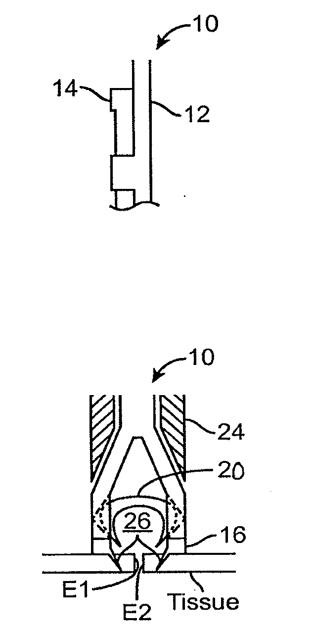
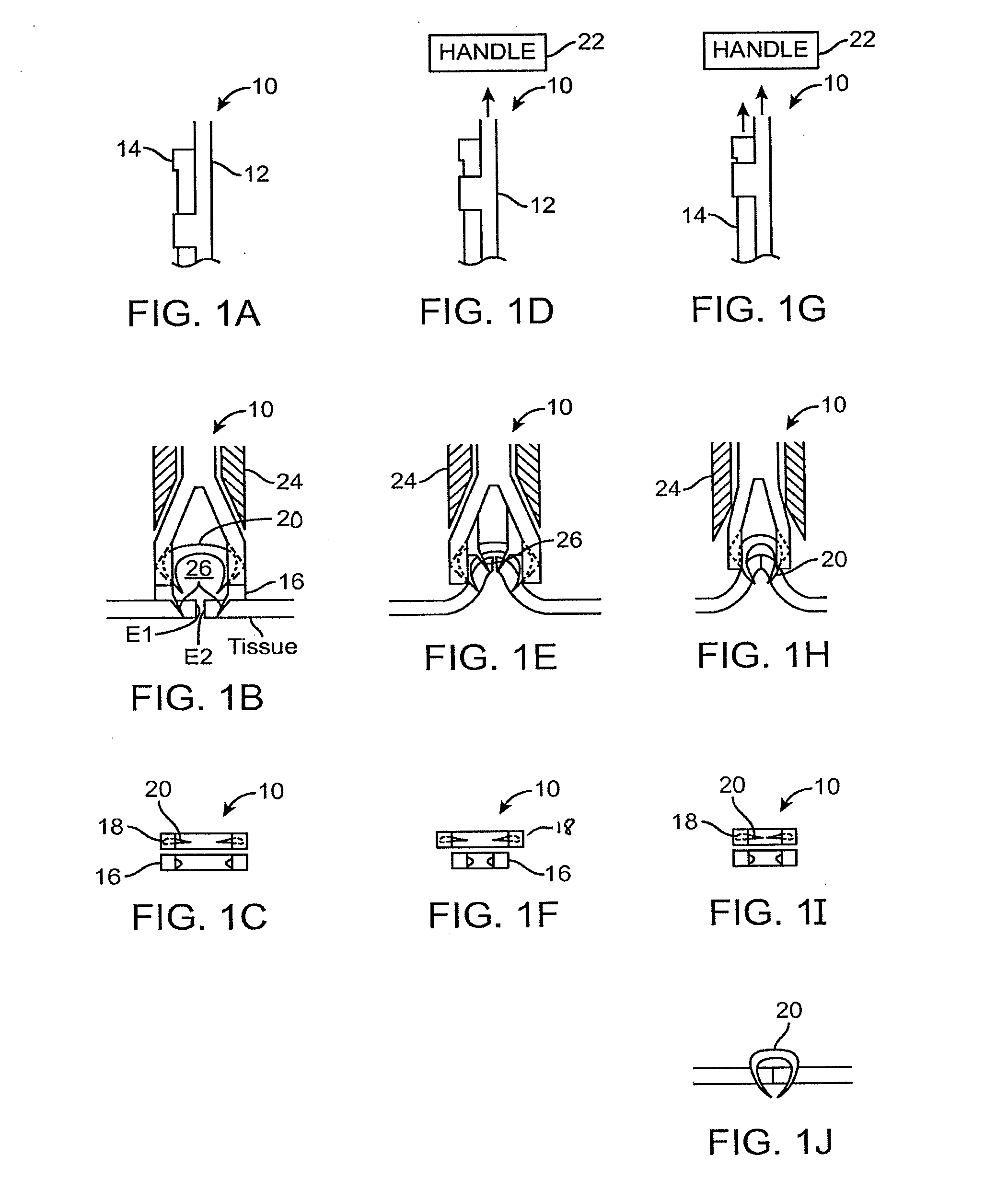
[0096]FIGS. 1A-1J illustrates an exemplary embodiment 10 of an apparatus (mechanism) for simultaneously grasping and clipping together the edges E1, E2 of tissue that have been wounded or incised. The apparatus 10 may include two sets of stacked shafts 12, 14, each with a distal jaw 16, 18. One shaft 12 and jaw 16 are designed to grasp and pull together the edges of the tissue E1, E2. The second shaft 14 and jaw 18 are designed to carry a normally open malleable clip 20 that may be compressed by the jaws 18 to form a closed clip 20 to secure the two edges E1, E2 of tissue together. The stacked shafts 12, 14 may be connected to a handle 22 that provides fore and aft axial movement of each of the jaws 16, 18 against an anvil 24 that surrounds the shafts 12, 14.

[0097]In operation of the exemplary embodiment in FIGS. 1A-1C, as the grasping shaft 12 is pulled by the handle, the jaws 16 of the grasping shaft 12 interfere with the anvil 24 and are compressed. Hooks or protrusions 26 at the...

exemplary embodiment 30

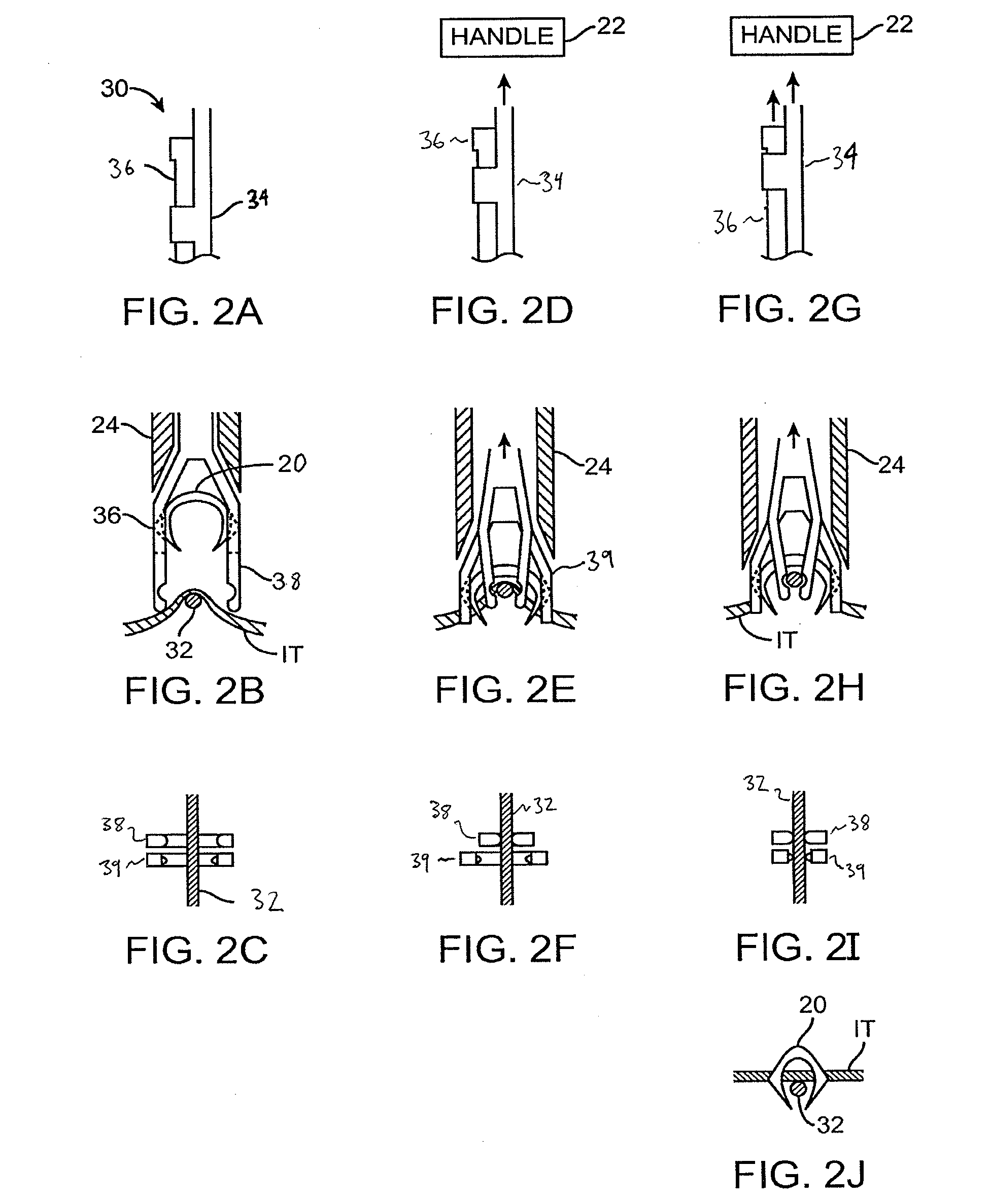
[0098]FIGS. 2A-2J illustrates an exemplary embodiment 30 of an apparatus for simultaneously grasping and clipping together prosthesis 32 to ophthalmic tissue. The embodiment illustrates, by example, the fixation of an intraocular lens haptic 32 (prosthesis) to iris tissue IT. The apparatus in FIGS. 2A-2J may include two sets of stacked shafts 34, 36, each with a distal jaw. One shaft 34 and jaw is designed to grasp and draw the tissue IT and prosthetic 32 toward the distal instrument. The second shaft 36 and jaw is designed to carry a normally open malleable clip 20 that can be compressed by the jaws to form a closed clip 20 to secure the intraocular lens haptic 32 to the iris IT. The stacked shafts 34, 36 may be connected to a handle 22 that provides fore and aft axial movement of the jaws against an anvil 24 that surrounds the shafts.

[0099]In operation of the exemplary embodiment in FIGS. 2A-2C, as the grasping shaft 34 is pulled by the handle 22 in operation, the jaws 38 of the g...

exemplary embodiment 40

[0100]FIGS. 3A and 3B illustrate an exemplary embodiment 40 of the apparatus in which the forceps 42 to apply the ophthalmic clip 20 may be positioned at an angle, on a plane, approximately tangent to the surface of the eye E and the clip 20 may be positioned approximately perpendicular to the tissue to be closed or fixated. The apparatus 40 includes forceps 42 may include jaws for securing a normally open malleable clip. In exemplary operation, when the handles 44 of the forceps 42 are squeezed together, the hinged forceps jaws 46 are drawn together, which close the malleable clip 20. A leaf spring 48 or other spring may be coupled to the handles 44 of the forceps 42 to keep the jaws 46 in a normally open position until the surgeon desires to deploy the clip 20. Once the clip 20 is deployed, the surgeon may release pressure on the handles 44 such that the spring returns the forceps 42 to the open position leaving the clip 20 in place on the tissue and allowing for removal of the fo...


PUM

PropertyMeasurementUnit
diameteraaaaaaaaaa
diametersaaaaaaaaaa
diametersaaaaaaaaaa

Abstract

Improved tissue fasteners are disclosed that can be inserted into (and optionally through) tissue structures underlying a tissue surface for affixing overlapping tissues and tissue planes together, and the like. In some embodiments, an elongate anvil body may protrude distally and / or laterally from a fastener support disposed along the base. The anvil body may have a sharpened end and be configured to penetrate into the tissue, with the elongate anvil body optionally having a bend from a more distal orientation adjacent the clip support to a more lateral orientation adjacent the sharpened end during at least a portion of the deployment. The first leg can be driven through a desired location on the surface of the first tissue and against a receptacle of the anvil body so as to deform the fastener and affix it to the first tissue.

Description

CROSS-REFERENCES TO RELATED APPLICATIONS[0001]This application is a continuation of U.S. Non-Provisional application Ser. No. 13 / 709,375 filed on Dec. 10, 2012, which claims the benefit of U.S. Provisional Application No. 61 / 568,549 filed on Dec. 8, 2011, and of U.S. Provisional Application No. 61 / 709,554 filed on Oct. 4, 2012. The full disclosures, each of which are incorporated herein by reference in their entirety for all purposes.[0002]The subject matter of the present application is related to that of U.S. Provisional Application No. 61 / 468,827 filed Mar. 29, 2011, and U.S. Non-Provisional application Ser. No. 13 / 434,562 filed Mar. 29, 2012. The full disclosures, each of which are also incorporated herein by reference in their entirety for all purposes.FIELD OF THE INVENTION[0003]The present invention relates generally to medical devices, systems and methods, with many of the embodiments described herein providing and / or employing fasteners such as clips, staples, or the like, ...

Claims


Application Information

Patent Timeline
Patent Type & Authority Applications(United States)
IPC IPC(8): A61B17/068
CPCA61B17/0682A61B17/068A61B17/0686A61B17/0684A61F9/007A61B2017/00867A61B2017/0645A61B2017/2918A61F2/16A61B17/105A61B2017/00743
Inventor VOLD, STEVEN D.PEARTREE, KENNETH A.BUCKLEY, TIMOTHY D.FEUSTEL, AARON
Owner O3 OPTIX LLC
Why Eureka
Try Eureka