

Geometrical elements transformed by rigid motions
Active Publication Date: 2014-07-03
DASSAULT SYSTEMES
View PDF1 Cites 16 Cited by
- Summary
- Abstract
- Description
- Claims
- Application Information
AI Technical Summary
Benefits of technology
This patent is about a computer-implemented method for designing 3D modeled objects. The method involves creating a graph with nodes and arcs that represent the geometrical elements of the object. The arcs represent the motion that transforms one geometrical element into another. The method then identifies the most important parts of the object by looking for sub-graphs with high numbers of arcs and respect for the identity criterion. These sub-graphs are then collapsed and tested to confirm their importance. The method can also be used to create new sub-graphs with the most important parts removed, and a computer program and system for implementing this method are also provided. The technical effect of this patent is to improve the efficiency and accuracy of 3D modeling by automating the process of identifying the most important parts of an object.
Problems solved by technology
In such a case, for efficiency purposes, the history of the solid is generally not available to the user.
Consequently, feature recognition is unavoidable, even in the “direct editing” field.
Thus, the existing solutions lack efficiency, notably from a user utilization point of view and from an exhaustiveness point of view.
Method used
View moreImage
Smart ImageViewing Examples

Examples
case 1
[0087 leads to u1˜u3 because relation ˜ is transitive, and then u1≈u3.
case 2
[0088 is equivalent to u1˜u2 and u2˜u3−1 by inversion property. Since ˜ is transitive, u1˜u3−1 which is equivalent to u1−1˜u3 by inversion property again, meaning that u1≈u3.
case 3 leads
[0089 to u1−1˜u3 because ˜ is transitive, meaning that u1≈u3.
Login to View More PUM
 Abstract
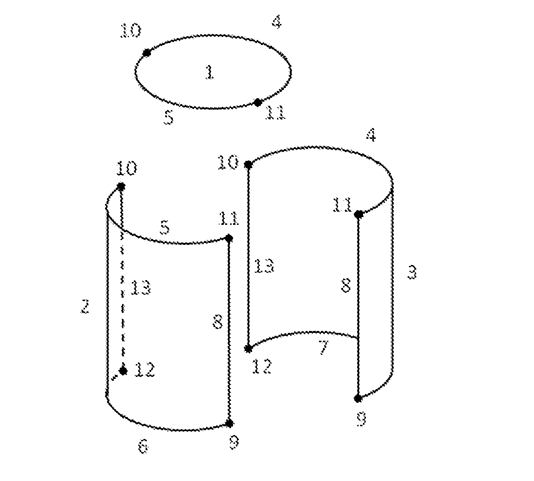
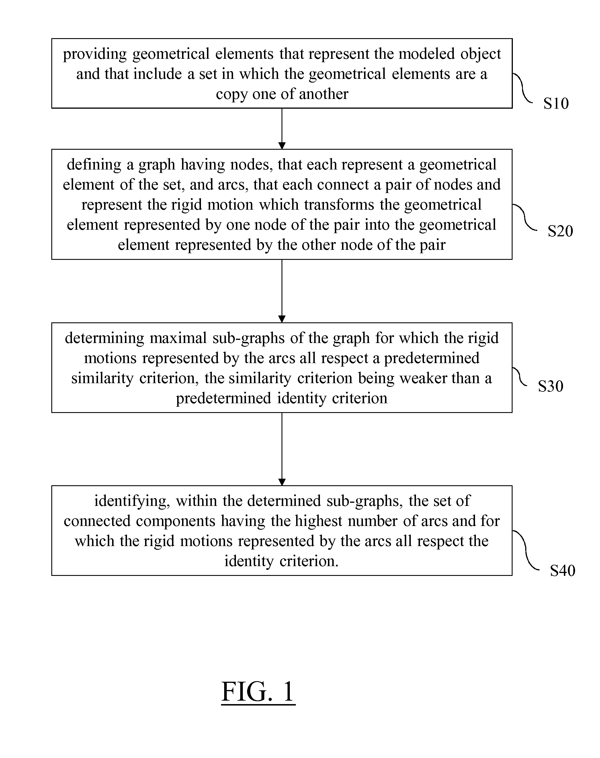
It is provided a computer-implemented method for designing a three-dimensional modeled object. The method comprises providing geometrical elements that represent the modeled object and that include a set in which the geometrical elements are a copy one of another. The method also comprises defining a graph, determining maximal sub-graphs of the graph, and identifying, within the determined sub-graphs, the set of connected components having the highest number of arcs and for which the rigid motions represented by the arcs all respect the identity criterion. Such a method improves the design of a 3D modeled object.
Description
RELATED APPLICATION(S)[0001]This application claims priority under 35 U.S.C. §119 or 365 to European Application No. 12306721.7, filed Dec. 31, 2012.[0002]The entire teachings of the above application(s) are incorporated herein by reference.FIELD OF THE INVENTION[0003]The invention relates to the field of computer programs and systems, and more specifically to a method, system and program for designing a three-dimensional (3D) modeled object.BACKGROUND OF THE INVENTION[0004]A number of systems and programs are offered on the market for the design, the engineering and the manufacturing of objects. CAD is an acronym for Computer-Aided Design, e.g. it relates to software solutions for designing an object. CAE is an acronym for Computer-Aided Engineering, e.g. it relates to software solutions for simulating the physical behavior of a future product. CAM is an acronym for Computer-Aided Manufacturing, e.g. it relates to software solutions for defining manufacturing processes and operatio...
Claims
Login to View More Application Information
Patent Timeline
 IPC IPC(8): G06T17/10
CPCG06T17/10G06T2210/61G06T17/005G06F30/00G06F30/12G06F30/18
InventorJANVIER, JEAN-BAPTISTE
OwnerDASSAULT SYSTEMES