
Touch panel

Active Publication Date: 2014-07-03
SAMSUNG ELECTRO MECHANICS CO LTD
View PDF5 Cites 14 Cited by
  • Summary
  • Abstract
  • Description
  • Claims
  • Application Information

AI Technical Summary

Benefits of technology

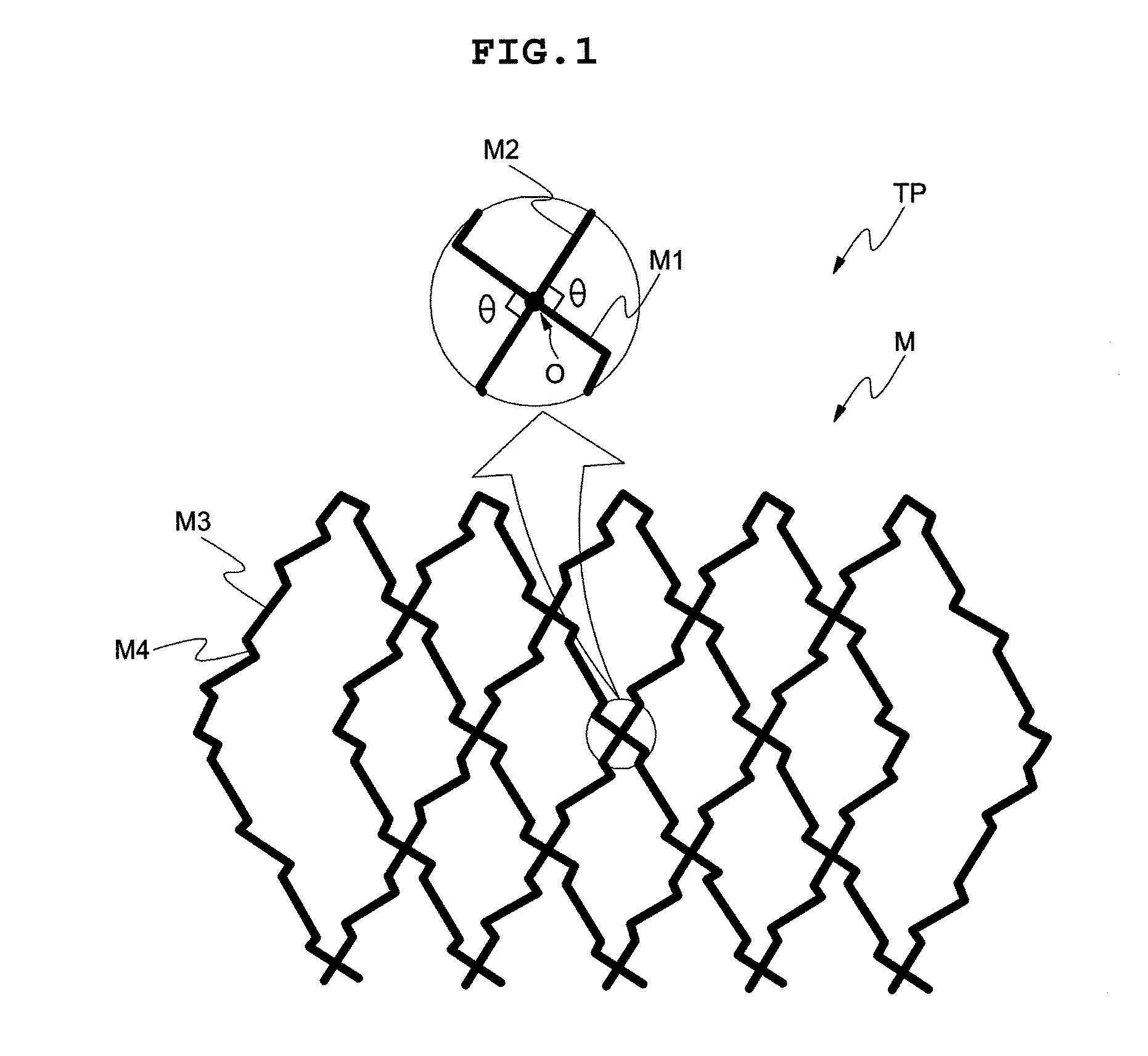
The present invention provides a touch panel where the angle between intersecting electrode patterns is 90 degrees, which reduces the contact area and visibility of the electrode pattern.

Problems solved by technology

However, since the use of the computer has gradually widened due to the rapid progress of an information-oriented society, there are difficulties in effectively driving products only using the keyboard and the mouse currently acting as an input device.
However, since ITO is generated as a byproduct from zinc (Zn) mine or the like, ITO may not be used in flexible materials such as polymer substance and the like due to its unstable supply and demand and lack of flexibility.
In addition, ITO should be fabricated under a high-temperature and high-pressure environment, and therefore production costs are increased.
Here, in the intersecting portion, a width of the electrode pattern may be relatively increased which causes an increase in a contact area, and therefore visibility of the electrode pattern may be increased due to non-uniformity of the pattern.

Method used

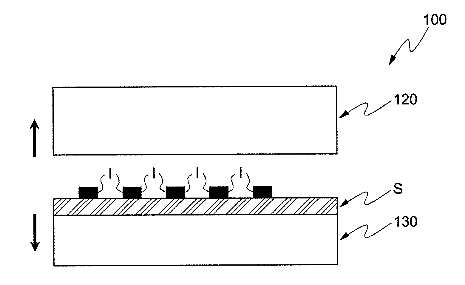
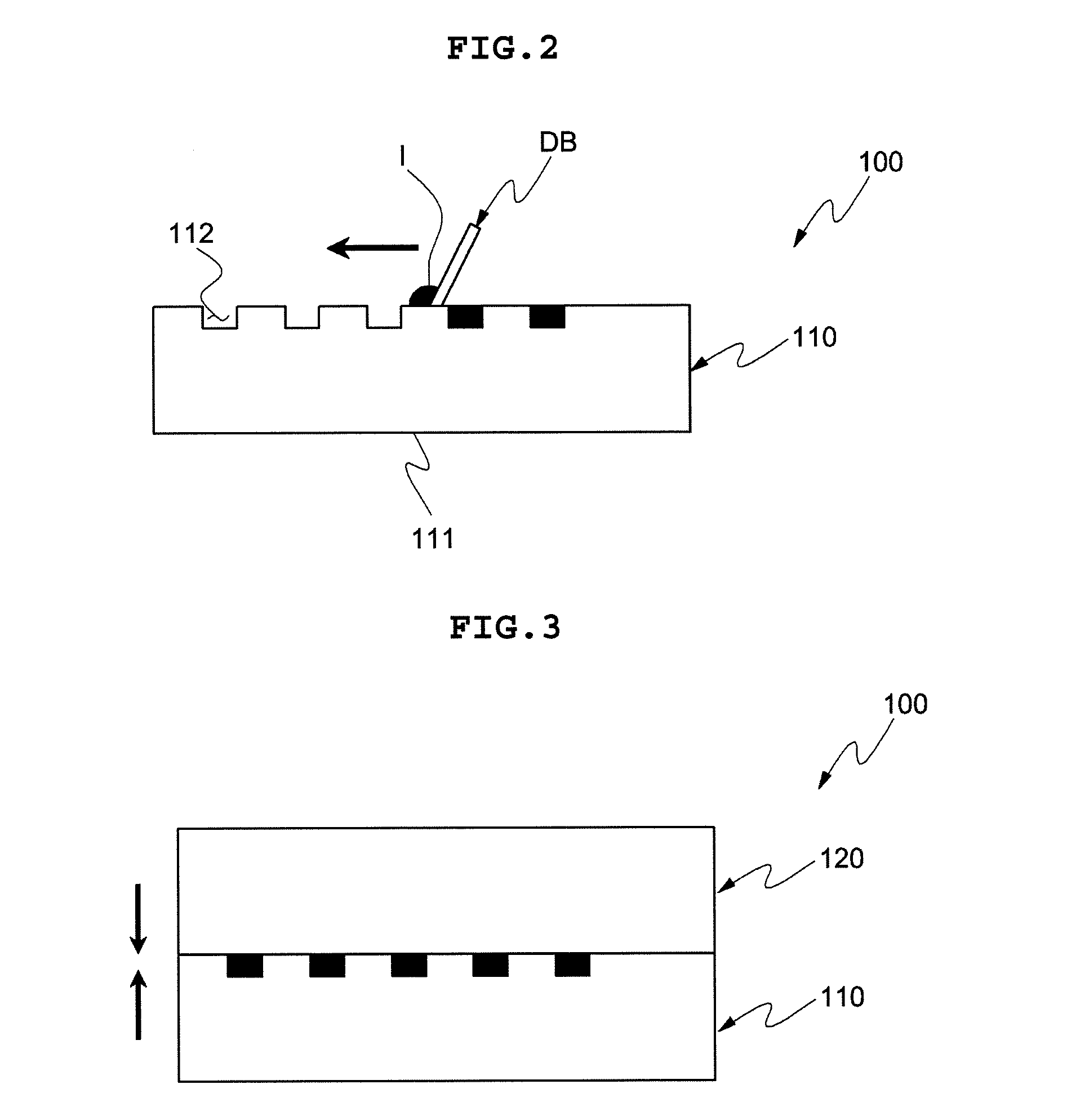

Image

  • Touch panel
  • Touch panel
  • Touch panel

Examples


Embodiment Construction

[0028]The objects, features and advantages of the present invention will be more clearly understood from the following detailed description of the preferred embodiments taken in conjunction with the accompanying drawings. Throughout the accompanying drawings, the same reference numerals are used to designate the same or similar components, and redundant descriptions thereof are omitted. Further, in the following description, the terms “first”, “second”, “one side”, “the other side” and the like are used to differentiate a certain component from other components, but the configuration of such components should not be construed to be limited by the terms. Further, in the description of the present invention, when it is determined that the detailed description of the related art would obscure the gist of the present invention, the description thereof will be omitted.

[0029]Hereinafter, preferred embodiments of the present invention will be described in detail with reference to the attac...


PUM


Abstract

Disclosed herein is a touch panel. In the touch panel, electrode patterns included in the touch panel may be orthogonal to each other in an intersecting point, and formed of a combination of unit patterns having a bent straight line shape. Accordingly, it is possible to prevent a contact area of the electrode patterns that intersect in the intersecting point from being increasing, thereby reducing visibility of the electrode pattern.

Description

CROSS REFERENCE TO RELATED APPLICATION[0001]This application claims the benefit of Korean Patent Application No. 10-2012-0154869, filed on Dec. 27, 2012, entitled “Touch Panel”, which is hereby incorporated by reference in its entirety into this application.TECHNICAL FIELD[0002]The present invention relates to a touch panel.DESCRIPTION OF THE RELATED ART[0003]With the development of computers using digital technology, computer-assisted devices have been developed, and personal computers, portable transmission devices, other information processing devices exclusive for individual, and the like perform a text and graphic process using a variety of input devices such as a keyboard, a mouse, and the like.[0004]However, since the use of the computer has gradually widened due to the rapid progress of an information-oriented society, there are difficulties in effectively driving products only using the keyboard and the mouse currently acting as an input device. Accordingly, there is a dema...

Claims


Application Information

Patent Timeline
IPC IPC(8): G02F1/1333
CPCG02F1/13338G06F3/0446G06F3/0448G06F2203/04103G06F2203/04112G06F3/041G02F1/133707G02F1/134336
Inventor OH, SANG HWANLEE, JIN UK
Owner SAMSUNG ELECTRO MECHANICS CO LTD
Learn More