Polarizing plate, Anti-reflective laminate, and image display system

Inactive Publication Date: 2017-03-09
NITTO DENKO CORP
View PDF10 Cites 2 Cited by
  • Summary
  • Abstract
  • Description
  • Claims
  • Application Information

AI Technical Summary

Benefits of technology

[0007]Public displays, which are permanently installed outdoors in order to provide an advertisement or information providing services, or to form a landscape, have been drawing attention as an application development of image display devices. A public display generally has a constitution in which an image display device is installed in a case with a cover glass for visual recognition fitted therein for protecting the device from the outdoor environment so as to visually recognize an image through the cover glass. Ho

Problems solved by technology

However, it has been known that such a constitution may cause a possible decrease of the visibility due to surface reflection.
When a reflective liquid crystal display device (including a transflective liquid crystal display device) or an EL display is incorpora

Method used


Image

  • Polarizing plate, Anti-reflective laminate, and image display system
  • Polarizing plate, Anti-reflective laminate, and image display system

Examples


examples

[0079]The present invention will be explained with reference to examples below; however, the present invention is not limited to the examples shown below.

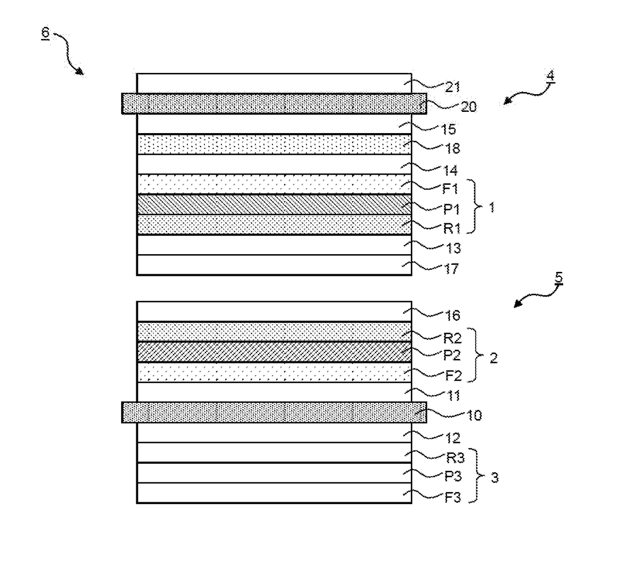
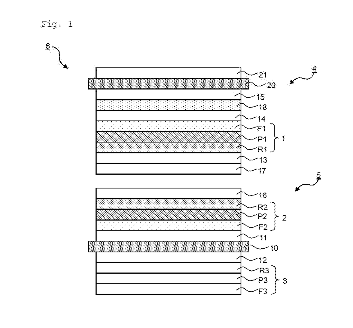
[0080]Polarizing plates 1A and 1B for anti-reflective laminate for pasting to an image display device were produced in the following procedure.

(Polarizing Plate 1A)

[0081]A polyvinyl alcohol (PVA) film having a thickness of 60 μm (product name “VF-PE #6000” manufactured by Kuraray Co., Ltd.) was stretched to 3 times between rolls each having a different speed ratio while being dyed in a 0.3 wt % iodine solution at 30° C. for 1 minute. Then, the film was further stretched so that a total stretching ratio became 6 times while being immersed in an aqueous solution containing 4 wt % boric acid and 5 wt % potassium iodide at 60° C. for 0.5 minutes. Next, the stretched film was immersed in an aqueous solution containing 3 wt % potassium iodide at 30° C. for 10 seconds for cleaning, and dried at 50° C. for 4 minutes to obtain a PVA film ha...


PUM

PropertyMeasurementUnit
Optical reflectivityaaaaaaaaaa
Transparencyaaaaaaaaaa
Optical reflectivityaaaaaaaaaa

Abstract

The present invention provides a polarizing plate and an image display system capable of lowering the reflectivity and improving the visibility of a public display. The present invention relates to a polarizing plate which is disposed on a visual recognition side of an image display devise that emits circularly polarized light and which converts the circularly polarized light into linearly polarized light. The polarizing plate preferably has a first optical element and a first polarizer in this order from an incident side of the circularly polarized light. The polarizing plate preferably has a λ/4 plate disposed closer to the visual recognition side than the first polarizer.

Description


Claims


Application Information

Patent Timeline
IPC IPC(8): G02B27/28G02B5/20G02B5/30G02B1/14
CPCG02B27/286G02B5/3083G02B5/208G02B1/14G02B1/11G02B5/283G02B5/3033
Inventor MURAYAMA, SHUNSUKEYAMASHITA, TOMOHIROKIMURA, MAKIKONAKATA, MIE
Owner NITTO DENKO CORP
Why Eureka
Try Eureka