Simulated weapon using holographic images

Inactive Publication Date: 2001-03-27
KAUTH CHRISTOPHER
View PDF12 Cites 3 Cited by
  • Summary
  • Abstract
  • Description
  • Claims
  • Application Information

AI Technical Summary

Benefits of technology

The center of such projected images is seen by looking along a ray perpendiclar to the surface of the hologram and whose origin is at the center of the hologram. The axis of the invention runs parallel to the length of the invention, and more exactly, parallel to both side panels and the top and bottom panels and is equidistant between the side panels and is equidistant between the top and bottom panels. The hologram and the images it projects are positioned correctly when the center-of-image ray is included in the axis of the invention; the body of the invention is perpendicular to the plane of the hologram. The lighting system or arrangement then is largely confined to the space behind the hologram as too much bulk extending beyond that region of space will tend to diminish the weapon-like appearance of the invention. Since direct lighting of the hologram reduces the visibility of the projected images, a means must be found to employ a lamp in the space behind the hologram without having it light the hologram directly. Because direct lighting is precluded an access channel for light rays to reach the surface of the hologram must also be provided. The invention employs an arrangement of light baffles positioned between the lamp and the hologram so no direct access to the hologram by light rays emitted by the lamp is possible. In addition, the light baffles define channels which allow light rays emitted by the lamp to reach the hologram by sequential reflection off the two mirrors. The channel formed by the mirrors and the light baffles not only provides a means of reaching the hologram for light rays emitted by the lamp, but also controls the angle at which the light rays are are incident upon the hologram. That angle must be and is predetermined both for the lighting arrangement and the hologram. The particular angle selected can be the result of many considerations pertaining to both holography and the design of the simulated weapon in other respects. The sharply defined channel formed by the light baffles and mirrors also tends to eliminate stray light rays so that all light rays striking the hologram are substantially parallel. Typically, in order to obtain good holographic images, it is necessary not only to control the angle at which the light rays are incident upon the hologram, but it is necessary also to assure that the incident light rays are substantially parallel. While holograms can be produced which require alternative lighting arrangements, such as a different angle of incidence for every point on the hologram's surface, in general, to facilitate flexibility in subsequent use holograms are made so that they are properly lighted with substantially

Problems solved by technology

(Real laser beams are invisible under most circumstances, so such laser weapons as might exist are poor model

Method used


Image

  • Simulated weapon using holographic images
  • Simulated weapon using holographic images
  • Simulated weapon using holographic images

Examples


Example

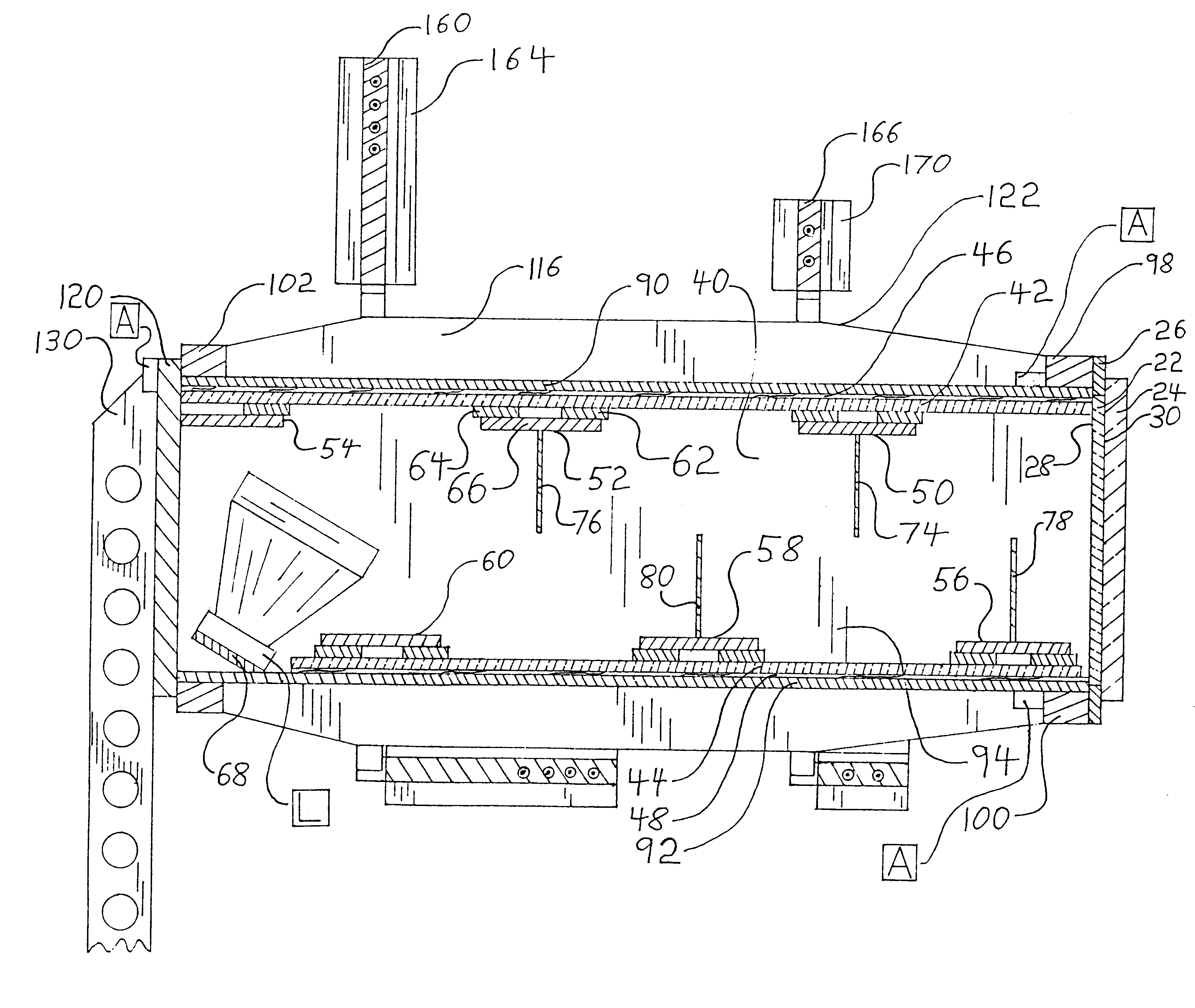
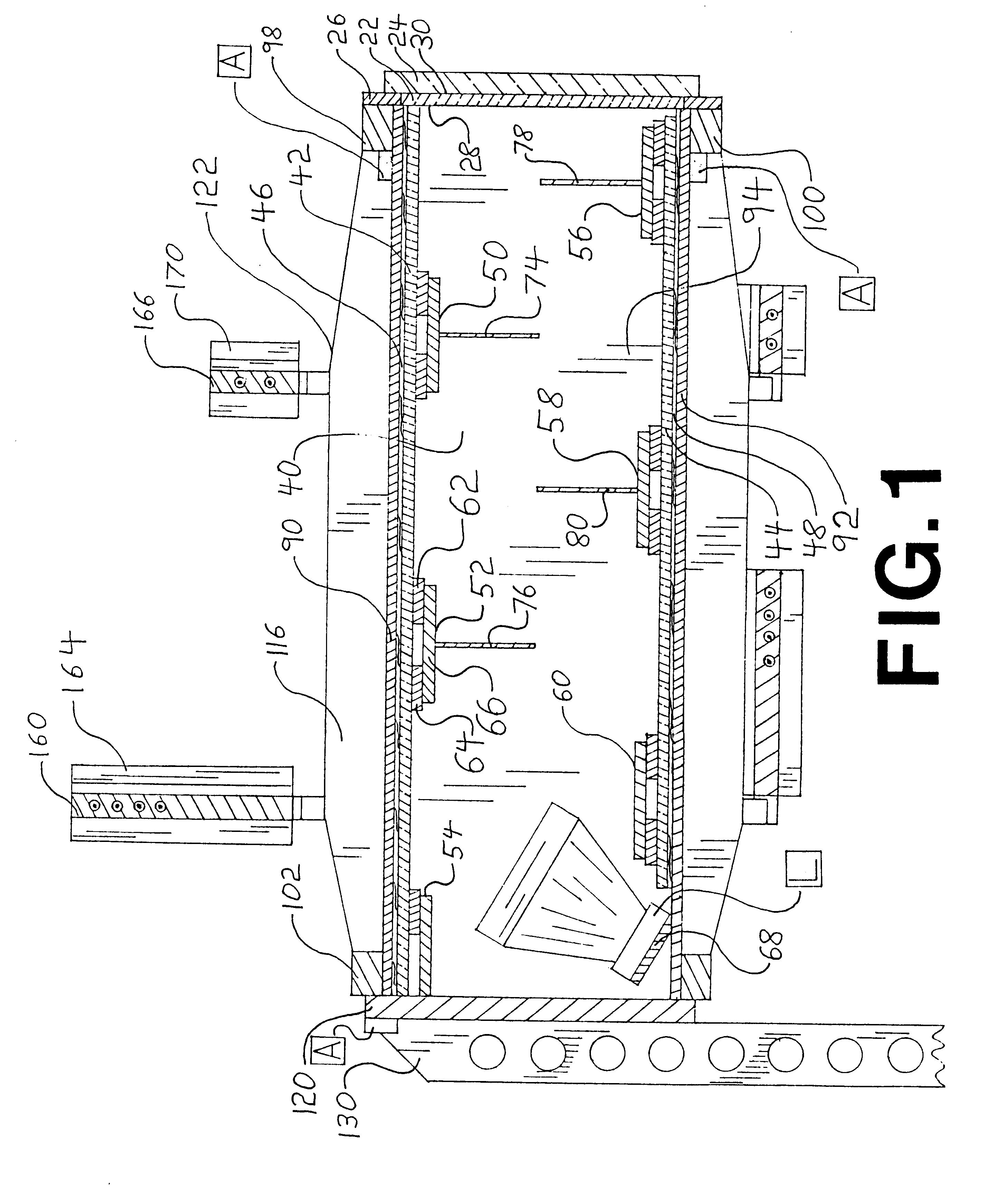
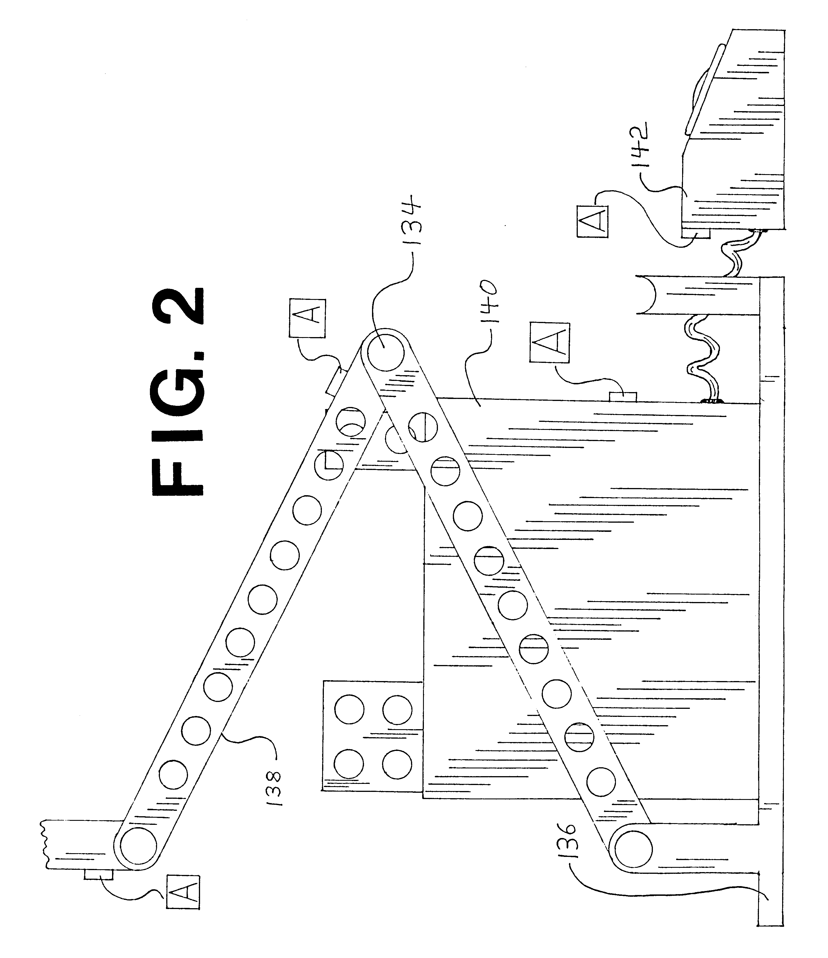
Referring to FIG. 1 and FIG. 2 it can be seen that structurally the invention consists of a body structure assembly 122 and a support structure assembly 138. Support structure assembly 138 supports body structure assembly 122 and controls the orientation of body structure assembly 122. Body structure assembly 122 positions most of the functional components of the invention and encloses many of those components.

A hologram 22 is held against longitudinal movement by a color filter 24 and the forward edges of body structure assembly 122. Hologram 22 is secured against transverse movement by a sash 26. Both color filter 24 and sash 26 are fastened to body structure assembly 122.

Hologram 22 at the margins of a first surface 28 impinges on the forward edges of body structure assembly 122. The remainder of the first surface 28 is adjacent to an interior chamber 40. Color filter 24 impinges on the entirety of a second surface 30 of hologram 22.

Interior chamber 40 is defined by a side panel ...


PUM


Abstract

A simulated weapon is disclosed which uses a hologram, an electric lamp and various other optical components to produce holographic images resembling the rays or beams of ray guns or space guns as portrayed in motion pictures, television programs, video games, and comic books in that the rays extend into and occupy space in front of the device itself but are not tangible. Sound effects accompany the projection of holographic images. The device also provides ancillary visual effects prior to the display of holographic images. Sound effects accompany the ancillary visual effects. The toy is intended for floor use and can be mounted on toy tank treads or other conveyance means. The rays are visible to those sitting, kneeling, or standing in front of the device. The preferred embodiment of the device is powered by an electric storage battery.

Description

1. Field of the InventionThis invention relates to simulated weapons. The use of holographic images and accompanying sound effects allows the invention to replicate the overall effects associated with a variety of simulated weapons. The invention is particularly suited for use as a simulated weapon intended to resemble a laser-type gun, ray gun, or space gun weapon such as portrayed in motion pictures, television programs, and video games.2. Description of Prior ArtSimulated weapons which employ visual effects, particularly those using vivid lighting, are well known. Devices which replicate conventional firearms have used flashing lights, often in conjunction with other effect to suggest muzzle flashes. Machine gun-type simulated weapons from the 1950s used flashing red lights together with a reciprocating plastic cylinder to imitate muzzle flashes. That visual effect involved both electric lighting and the extension into space of a physical object. Through its very rapid in-and-out...

Claims


Application Information

Patent Timeline
IPC IPC(8): A63H33/22A63H5/04A63H5/00
CPCA63H5/04A63H33/22A63F2250/302
Inventor KAUTH, CHRISTOPHER
Owner KAUTH CHRISTOPHER
Why Eureka
Try Eureka