Image display device

a technology of image display and display screen, which is applied in the direction of optics, instruments, optical elements, etc., can solve the problems of deterioration of aberrations, easy to notice distortion in the projected image due to distortion, and increase in the magnification ra

Active Publication Date: 2014-07-03
RICOH KK
View PDF11 Cites 14 Cited by
  • Summary
  • Abstract
  • Description
  • Claims
  • Application Information

AI Technical Summary

Benefits of technology

[0122]A zoom lens used in an image display device of the invention is a “projection zoom lens” as described above.

Problems solved by technology

Also, since an image to be projected is a magnified image, distortion in the projected image due to distortion is easily-noticeable.
A reduction in the displacement area of the moved groups results in an increase in a rate of change in the magnification.
As a result, aberrations are likely to be deteriorated.
When the first lens group is heavy, not only the projection zoom lens itself becomes heavy but also “eccentricity caused by its own weight” may occur in the first lens group.

Method used


Image

  • Image display device
  • Image display device
  • Image display device

Examples


example 1

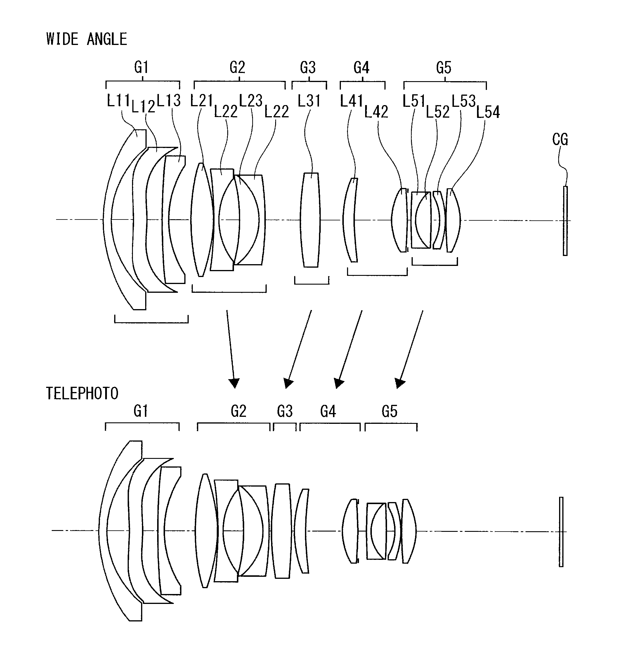
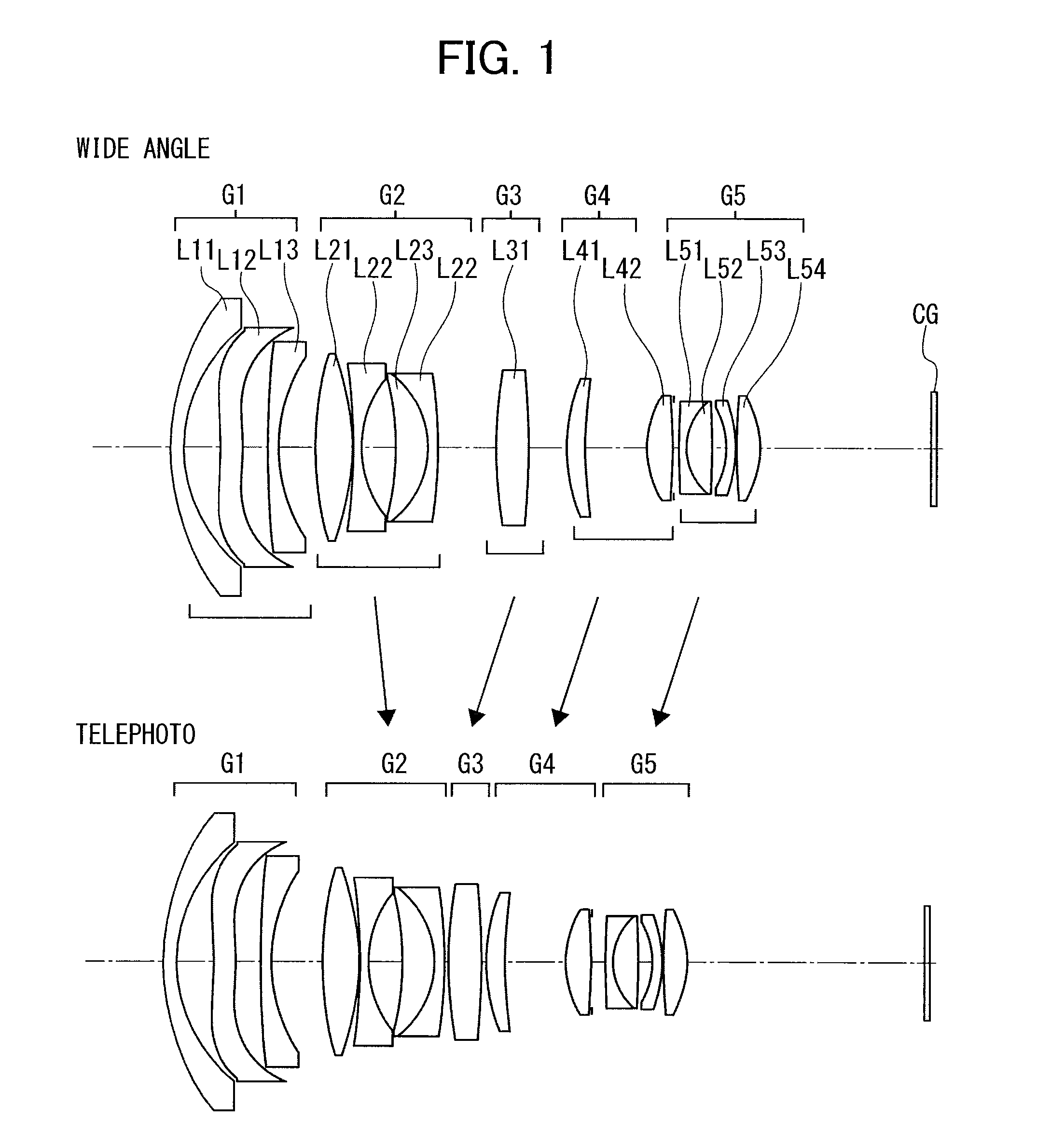
[0532]FIG. 1 shows a projection zoom lens of Example 1.

[0533]As shown in FIG. 1, a first lens group G1 includes lenses L11 to L13, and a second lens group G2 includes lenses L21 to L24.

[0534]A third lens group G3 includes one lens L31, and a fourth lens group G4 includes two lenses L41 and L42.

[0535]A fifth lens group G5 includes four lenses L51 to L54.

[0536]As described above, a DMD is assumed as a light bulb and has a cover glass CG

[0537]When the magnification is changed from the wide angle end to the telephoto end, the second lens group G2 is moved to the reduction side, and the third to fifth lens groups G3 to G5 are moved to the magnification side.

[0538]The first lens group G1 is a negative group, and includes a negative meniscus lens L11 convex toward the magnification side, a negative lens L12 concave toward the magnification side, and a negative meniscus lens L13 concave toward the reduction side.

[0539]The second lens group G2 is a negative group, and includes a biconvex len...

example 2

[0584]FIG. 3 shows a projection zoom lens of Example 2.

[0585]As shown in FIG. 3, a first lens group G1 includes lenses L11 to L13, and a second lens group G2 includes lenses L21 to L24.

[0586]A third lens group G3 includes one lens L31, a fourth lens group G4 includes lenses L41 and L42, and a fifth lens group G5 includes lenses L51 to L54.

[0587]When the magnification is changed from the wide angle end to the telephoto end, the second lens group G2 is moved to the reduction side, and the third to fifth lens groups G3 to G5 are moved to the magnification side.

[0588]The first lens group G1 is a negative group, and includes a negative meniscus lens L11 convex toward the magnification side, a negative lens L12 concave toward the magnification side, and a negative meniscus lens L13 concave toward the reduction side.

[0589]The second lens group G2 is a negative group, and includes a biconvex lens L21, a biconcave lens L22, a positive meniscus lens L23 convex toward the reduction side, and a...

example 3

[0619]FIG. 5 shows a projection zoom lens of Example 3.

[0620]As shown in FIG. 5, a first lens group G1 includes lenses L11 to L13, and a second lens group G2 includes lenses L21 to L24.

[0621]A third lens group G3 includes a lens L31, a fourth lens group G4 includes lenses L41 and L42, and a fifth lens group G5 includes lenses L51 to L54.

[0622]When the magnification is changed from the wide angle end to the telephoto end, the second lens group G2 is moved to the reduction side, and the third to fifth lens groups G3 to G5 are moved to the magnification side.

[0623]The first lens group G1 is a negative group, and includes a negative meniscus lens L11 convex toward the magnification side, a negative lens L12 concave toward the magnification side, and a negative meniscus lens L13 concave toward the reduction side.

[0624]The second lens group G2 is a negative group, and includes a biconvex lens L21, a biconcave lens L22, a positive meniscus lens L23 convex toward the reduction side, and a n...


PUM


Abstract

An image display device includes a high-performance projection zoom lens with a very wide field angle and an image display device including a projection zoom lens of a five-lens-group type, which achieves high performance across the entire zoom area. The image display device is configured to project an image onto a target projection surface and display a magnified image of the image, which uses a projection zoom lens having a five-lens-group configuration in which first to fifth lens groups G1 to G5 are arranged from the magnification side toward the reduction side, and each of the constituent lens groups or lenses included in the lens groups has a combination of negative and positive refractive powers, and in the lens configuration, focal lengths of the constituent lens groups, relative travel distances, lens distances to the image display element, and constituent lens shapes are properly selected.

Description

CROSS-REFERENCE TO RELATED APPLICATIONS[0001]The present application is based on and claims priority from Japanese Patent Application No. 2012-288362, filed on Dec. 28, 2012, and Japanese Patent Application No. 2012-289154, filed on Dec. 28, 2012, Japanese Patent Application No. 2012-289163, filed on Dec. 28, 2012, Japanese Patent Application No. 2012-289143, filed on Dec. 28, 2012, Japanese Patent Application No. 2012-289150, filed on Dec. 28, 2012, Japanese Patent Application No. 2013-095884, filed on Apr. 30, 2013, Japanese Patent Application No. 2013-095885, filed on Apr. 30, 2013, Japanese Patent Application No. 2013-124790, filed on Jun. 13, 2013, Japanese Patent Application No. 2013-209604, filed on Oct. 4, 2013, Japanese Patent Application No. 2013-209665, filed on Oct. 4, 2013, Japanese Patent Application No. 2013-209634, filed on Oct. 4, 2013, Japanese Patent Application No. 2013-209639, filed on Oct. 4, 2013, and Japanese Patent Application No. 2013-209645, filed on Oct. ...

Claims


Application Information

Patent Timeline
Patent Type & Authority Applications(United States)
IPC IPC(8): G02B13/04
CPCG02B13/16G02B15/177G02B15/145529G02B13/04G02B15/20
Inventor KUBOTA, TAKASHI
Owner RICOH KK
Why Eureka
Try Eureka