Data Remapping for Predictive Video Coding

a predictive video and data technology, applied in the field of video coding, can solve the problems that the adjacent reconstructed blocks are not good predictors of the current input block, and achieve the effect of maximizing similarity, minimizing coding costs, and minimizing coding costs

Inactive Publication Date: 2014-07-10
MITSUBISHI ELECTRIC RES LAB INC
View PDF7 Cites 14 Cited by
  • Summary
  • Abstract
  • Description
  • Claims
  • Application Information

AI Technical Summary

Benefits of technology

[0017]A coding cost can incorporate the maximization of similarity. Minimizing a coding cost can be equivalent to maximizing similarity or maximizing similarity along with minimizing another metric such as the number of bits used to represent the block m the bitstream.

Problems solved by technology

Therefore, the adjacent reconstructed blocks are not good predictors for the current input block.

Method used


Image

  • Data Remapping for Predictive Video Coding
  • Data Remapping for Predictive Video Coding
  • Data Remapping for Predictive Video Coding

Examples


Embodiment Construction

Encoder

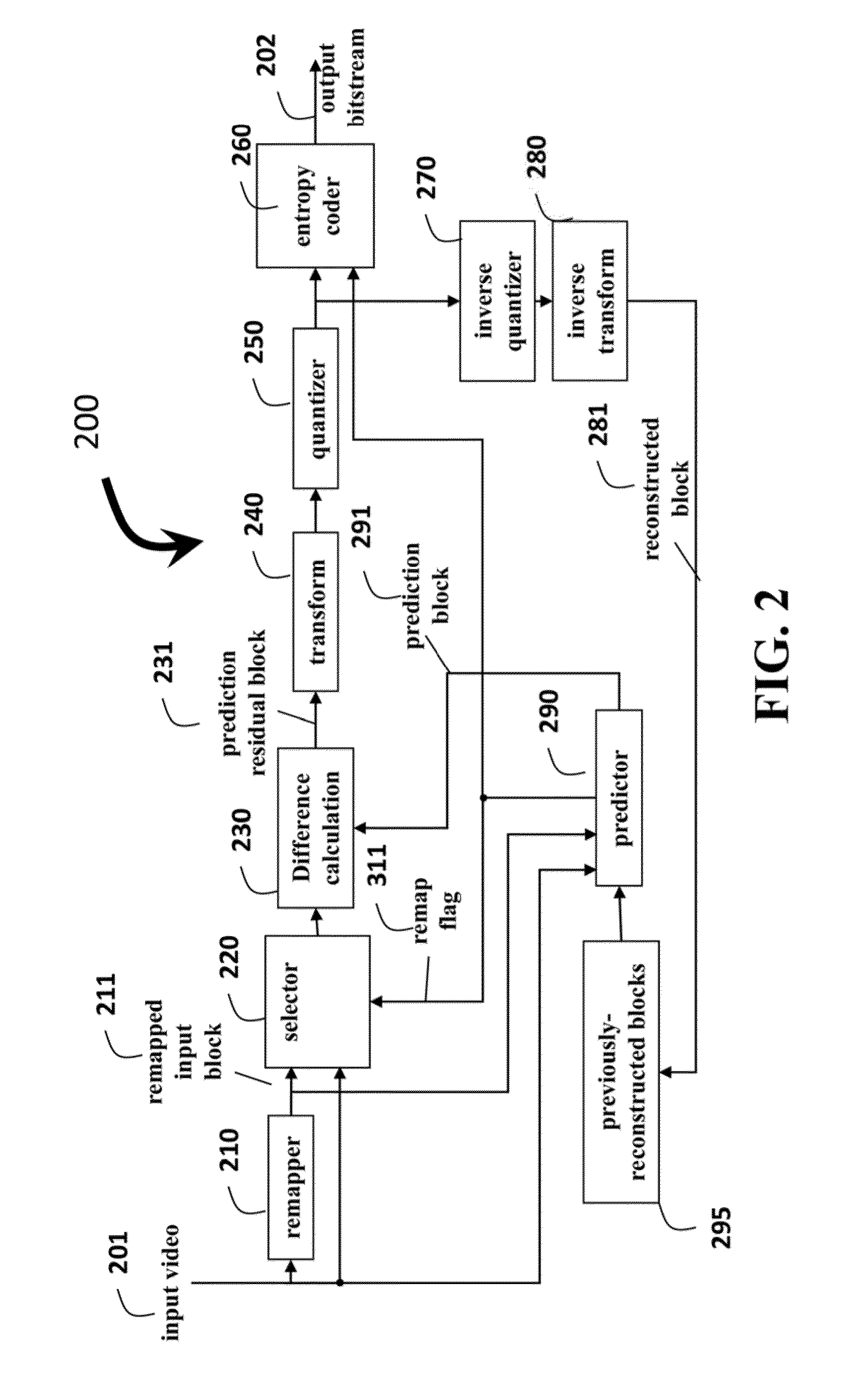
[0024]FIG. 2 shows a schematic of an encoder 200 according to the embodiments of the invention. The encoder can be implemented with a processor connected to memory and input / output interlaces by buses as known in the art.

[0025]A current block from pictures in an input video 201 to be encoded is input to a remapper 210 to produce a remapped input block 211. The remapped input block and the current input block are input to a selector 220.

[0026]A set (one or more) of previously reconstructed blocks 295, are input to a predictor 290 to determine a prediction block 291.

[0027]The prediction block is compared to both the current input block and the remapped input block. If the prediction block is similar to the current block, then a remap flag 311 is set to false, and the current block is input to a difference calculation 230. If the prediction block is more similar to the remapped input block, then the remap flag 311 is set to true, for convenience by the predictor 290, and the rem...


PUM


Abstract

Specifically, a method decodes a picture. The picture is encoded and represented by blocks in a bitstream. For each block, a remap flag is obtained from the bit-stream. The block is either a remapped reconstructed block or a non-remapped reconstructed block. Either the non-mapped reconstructed block or an inverse remapped reconstructed block is output according to the remap flag. The remapped reconstructed block maximizes a similarity with the neighboring blocks, as compared to the similarity of the non-mapped reconstructed block and the neighboring blocks, by applying point operations to the remapped reconstructed block.

Description

RELATED APPLICATION[0001]This Non-Provisional Application claims priority to U.S. Provisional Application Ser. No. 61 / 750,711, “Data Remapping for Predictive Video Coding,” filed by Cohen et al. on 9 Jan. 2013, which is incorporated herein by reference.FIELD OF THE INVENTION[0002]This invention relates generally to video coding, and more particularly to remapping data used during prediction processes.BACKGROUND OF THE INVENTION[0003]When videos, images, multimedia or other similar data are encoded or decoded, a set of previously reconstructed blocks of data are used to predict the block currently being encoded or decoded. The set can include one or more previously reconstructed blocks. A difference between a prediction block and the block currently being encoded is a prediction residual block. In the decoder, the prediction residual block is added to a prediction block to form a decoded or reconstructed block.[0004]In an encoder, the prediction residual block is a difference between...

Claims


Application Information

Patent Timeline
Patent Type & Authority Applications(United States)
IPC IPC(8): H04N7/32
CPCH04N19/00569H04N19/176H04N19/593H04N19/117H04N19/14H04N19/146
Inventor COHEN, ROBERT A.VETRO, ANTHONY
Owner MITSUBISHI ELECTRIC RES LAB INC
Why Eureka
Try Eureka