Polarity switching flow battery system and method

a battery system and flow technology, applied in the direction of electrolyte stream management, indirect fuel cells, non-aqueous electrolyte cells, etc., can solve the problems of reducing the overall efficiency of the battery, less suitable for small applications, and negligible effect of the battery efficiency

Inactive Publication Date: 2014-07-10
ASHLAWN ENERGY
View PDF2 Cites 19 Cited by
  • Summary
  • Abstract
  • Description
  • Claims
  • Application Information

AI Technical Summary

Benefits of technology

The patent describes a flow battery system that uses two storage tanks to transport electrolyte to the battery cells. The system includes a feed system to apply a negative charge to the electrolyte from the first tank and return it to the second tank, and a return system to apply a positive charge to the electrolyte from the second tank and return it to the first tank. The system also includes a controller to switch the polarity of the battery system to control which tank is being charged. The technical effect of this system is to enable efficient and controlled charging of the battery cells using a flow battery system.

Problems solved by technology

The technical problem addressed in this patent text is the inefficient mixing of electrolytes in flow battery systems due to the long down-time required for the system to cool down and the high pumping power required to transfer the contents of the storage tanks. The conventional method requires a long down-time for the flow battery system to reach its normal charged state. The residue ions are then lost during the mixing process, leading to a mixture of depleted ions and energy storage loss. The patent proposes a new method to address this issue by incorporating a three-port valve and mechanical mixers to improve the mixing process.

Method used


Image

  • Polarity switching flow battery system and method
  • Polarity switching flow battery system and method
  • Polarity switching flow battery system and method

Examples


Embodiment Construction

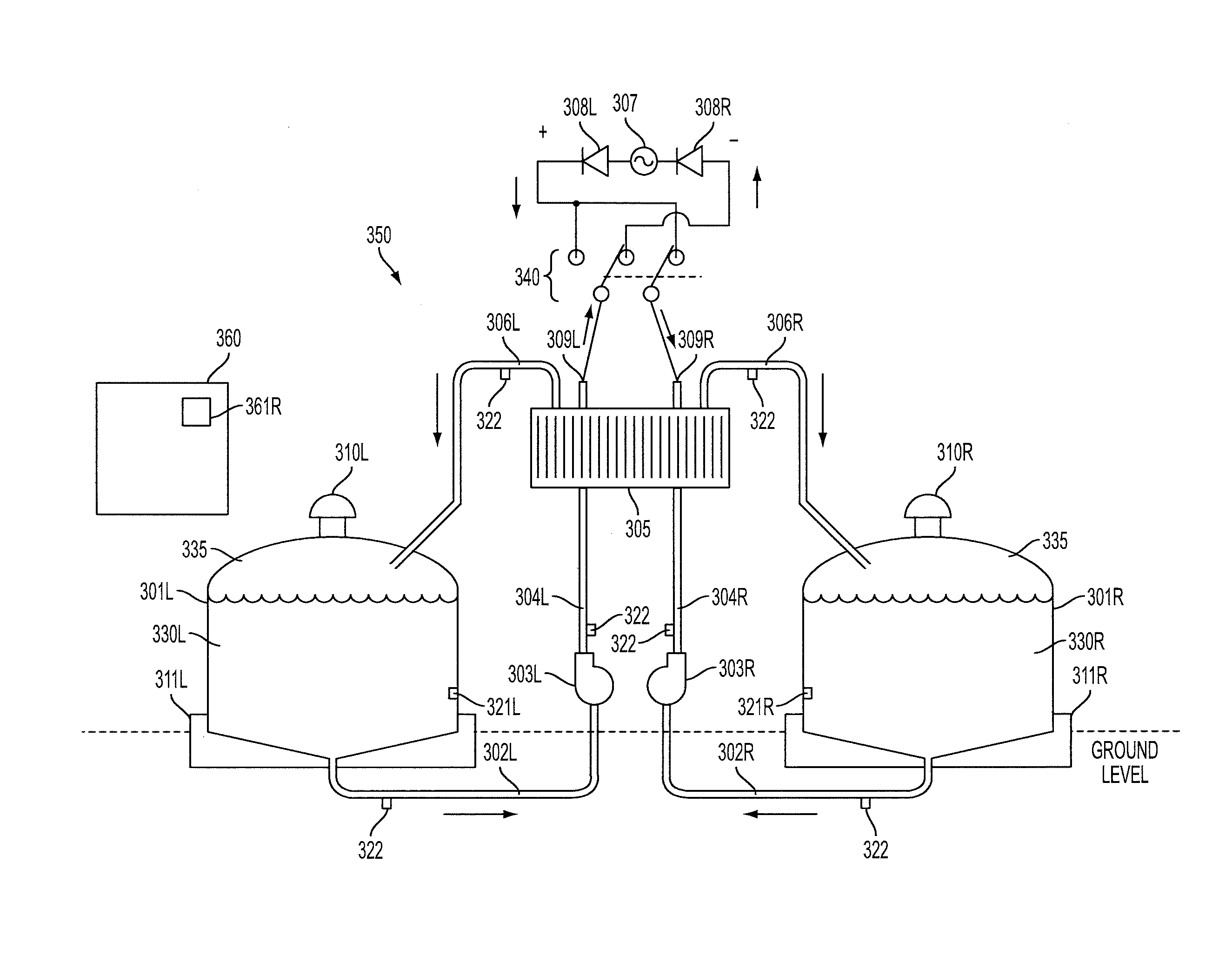
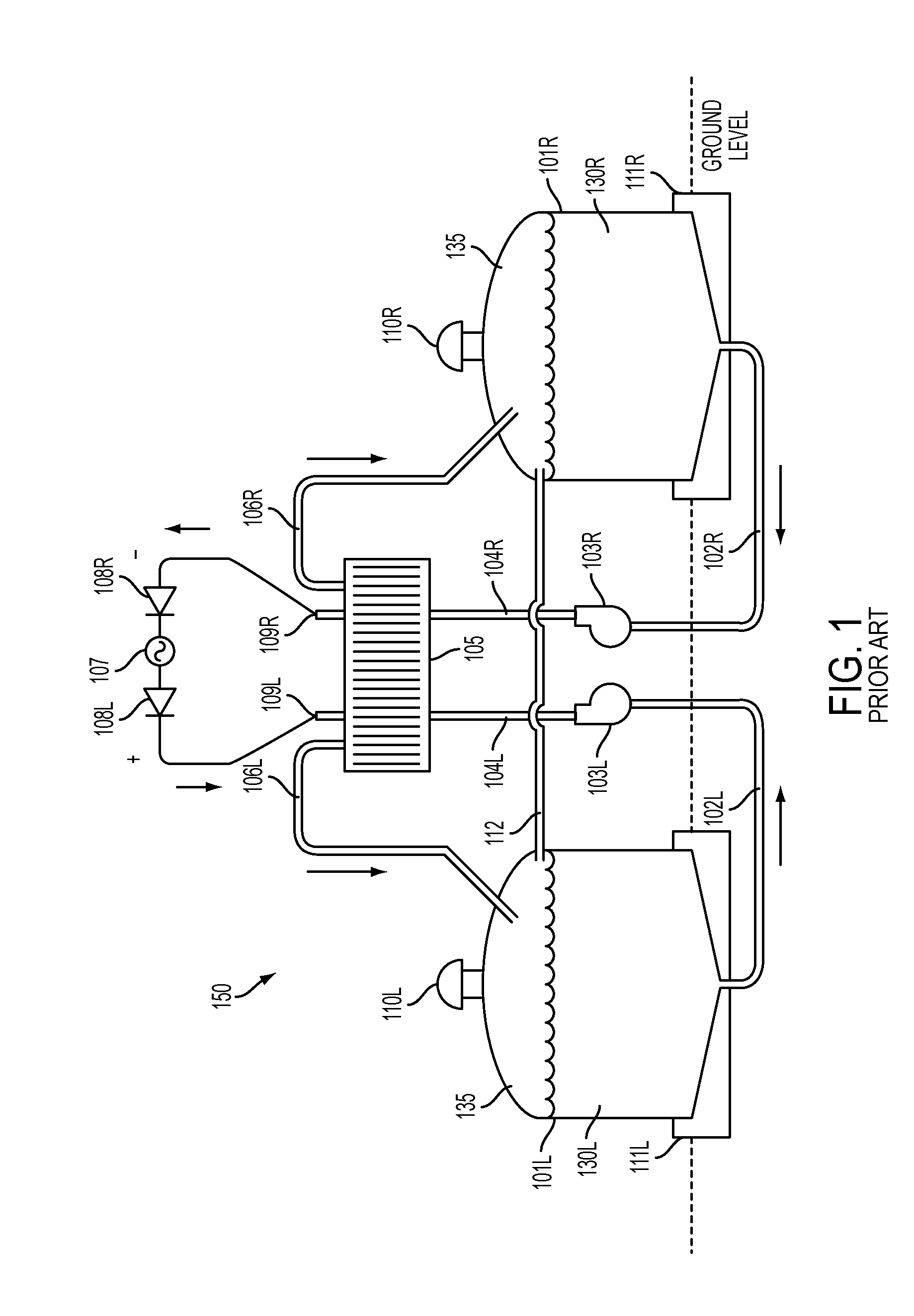
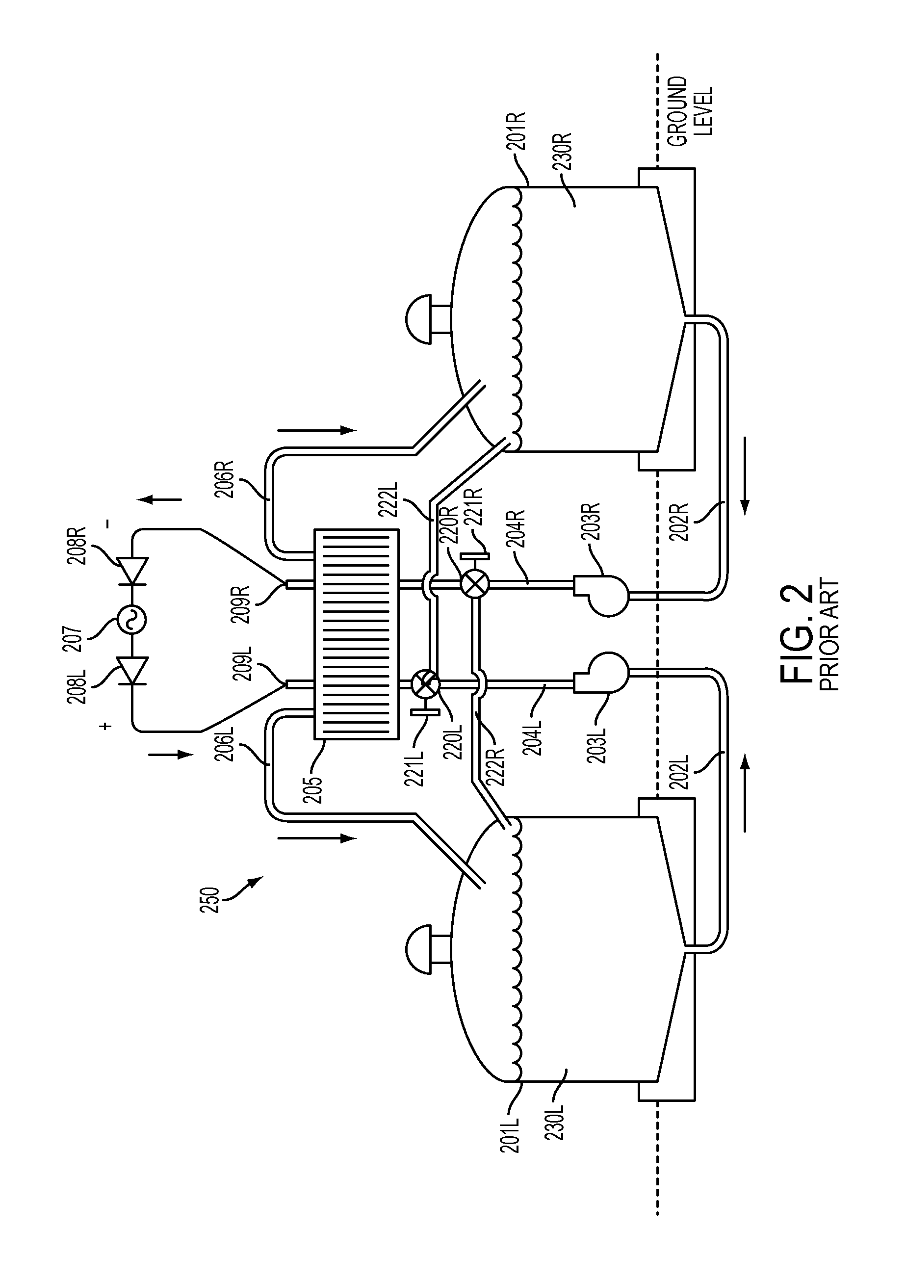
[0063]Reference will now be made in detail to one or more embodiments, illustrated in the accompanying drawings, wherein like reference numerals refer to like elements throughout. In this regard, embodiments of the present invention may be embodied in many different forms and should not be construed as being limited to embodiments set forth herein. Accordingly, embodiments are merely described below, by referring to the figures, to explain aspects of the present invention.

[0064]One or more embodiments relate to a redox flow battery system that may correct for determined ion reactant imbalance(s) that may occur between positive and negative electrolytes after prolonged periods of use. Depending on electrolyte solution, ions cross the battery membrane in both directions due to leakage through the membrane and due to corrections made for osmotic water transfer. These processes are asymmetric and generally result in a net excess of ions on the negative side of the flow battery when cati...


PUM


Abstract

A flow battery system and method are provided. The flow battery system may include a feed system feeding positive electrolyte from a first storage tank to a positive inlet of a battery stack and negative electrolyte from a second storage tank to a negative inlet of the battery stack, a return system returning charged electrolyte from the battery stack to the first and second storage tanks, and a controller to selectively control at least one of the feed system and the return system so positive electrolyte, from the first storage tank, is applied a negative charge by the battery stack and then returned by the return system to the second storage tank, and so negative electrolyte, from the second storage tank, is applied a positive charge by the battery stack and then returned by the return system to the first storage tank.

Description


Claims


Application Information

Patent Timeline
Owner ASHLAWN ENERGY
Why Eureka
Try Eureka