Fastening Apparatus
- Summary
- Abstract
- Description
- Claims
- Application Information
AI Technical Summary
Benefits of technology
Problems solved by technology
Method used
Image
Examples
first embodiment
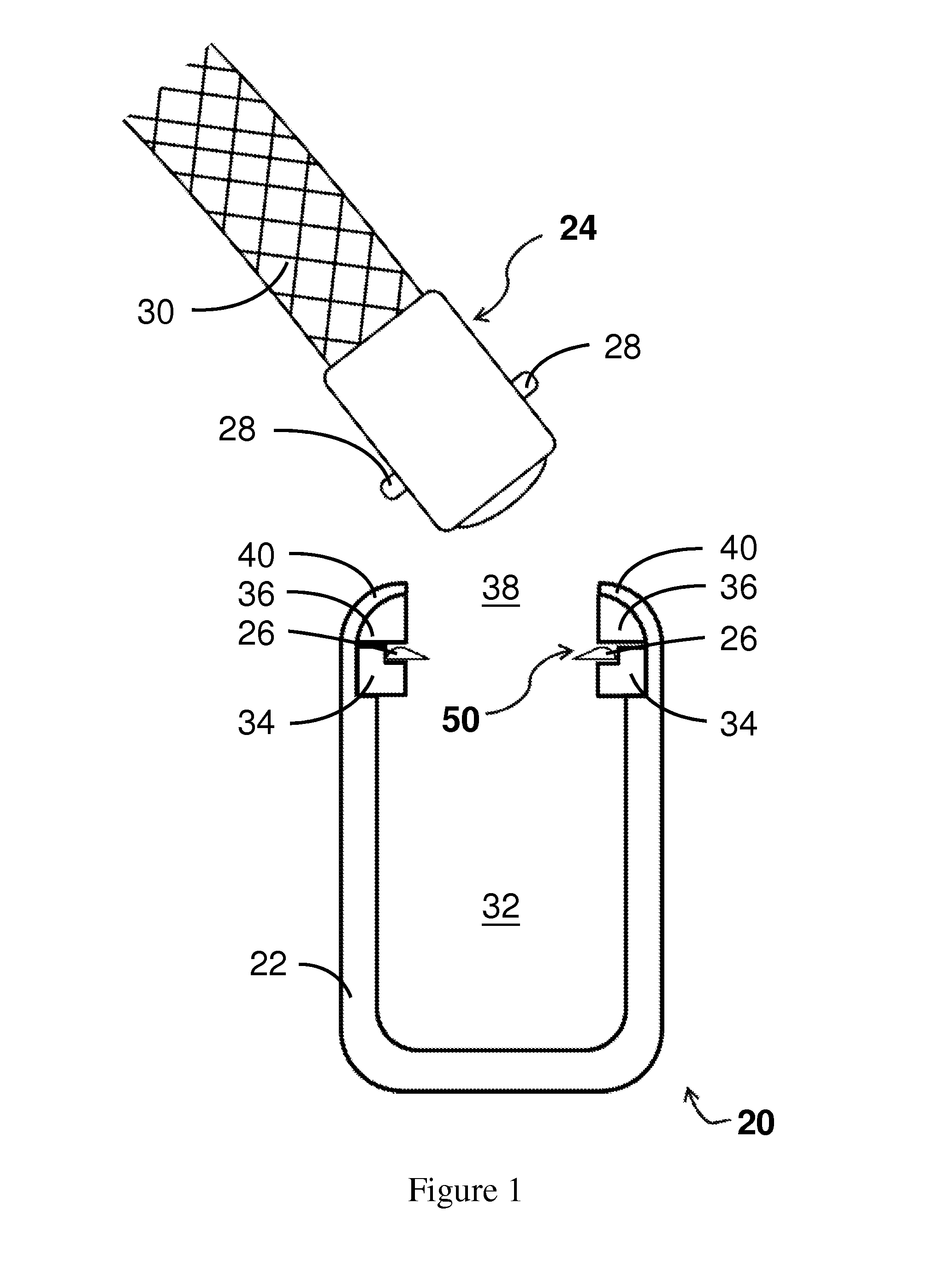
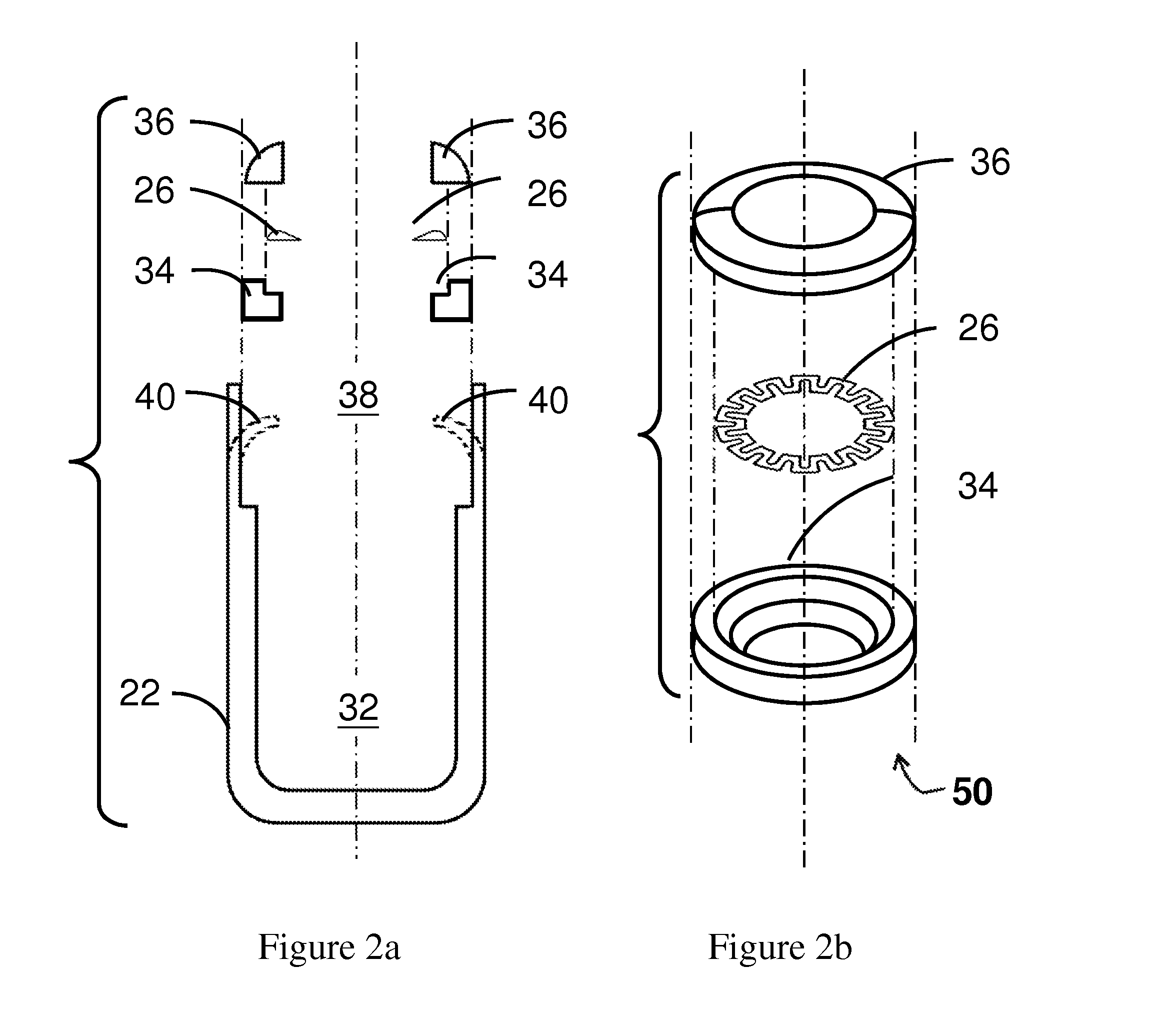
[0025]Referring first to FIG. 1, the first embodiment of the present invention is a fastening apparatus 20 for fastening two objects together. In one embodiment, the fastening apparatus 20 comprise a frame 22, a coupling device 24 and a retaining ring 26. The coupling device 24 further comprises an outwardly extended fringe 28 and a means to attach a string or a strip 30. The frame 22 comprises an opening 38, which is partially enclosed by an inwardly extended lip 40, and a cavity 32 for receiving the coupling device 24. An inner rim support 34 and a supporting ring 36 are assembled together with the retaining ring 26 to form a ring module 50.
[0026]Referring to FIGS. 2a and 2b, the ring module 50 is assembled with retaining ring 26 placed in between the inner rim support 34 and the supporting ring 36 in this embodiment. The edge of the frame 22 is bent to form the inwardly extended lip 40 after the ring module 50 is placed inside the cavity 32 of the frame 22 so that the retaining r...
second embodiment
[0029]Now referring to FIG. 5, the second embodiment of the present invention is a fastening apparatus specifically designed such that the coupling device 24 is releasable after being latched onto the cavity 132 of the frame 122.
[0030]In this embodiment, the fastening apparatus 120 comprises a frame 122, a coupling device 24, a retaining ring 126 and a releasing device 146. The supporting ring 136 is firmly clamped by the inwardly extended lips 140 of the frame 122 to hold the retaining ring 126 in a desirable position inside the cavity 132 of the frame 122. Moreover, the supporting ring 136 is configured to fittingly adapt to the releasing device 146 such that the releasing device 146 is latched onto the supporting ring 126 once it is inserted into the frame 122. In this embodiment, the releasing device 146 is superimposed on the protruding teeth 144 of the retaining ring 126.
[0031]The widest part of the coupling device 24 in this embodiment is larger than the aperture enclosed by ...
third embodiment
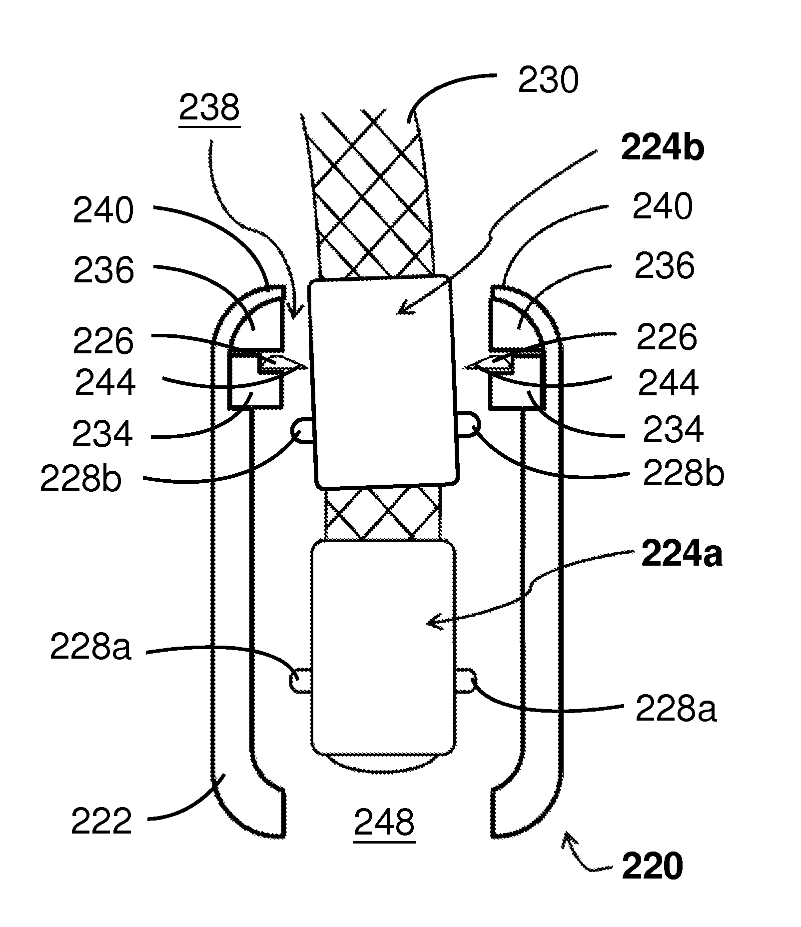
[0033]In yet another embodiment, as illustrated in FIG. 6, the fastening apparatus 220 is designed such that the fastening position and fastening strength can be adjusted. In one embodiment, the fastening apparatus 220 comprises a frame 222, two coupling devices 224a and 224b and a retaining ring 226. Both coupling 224a and 224b comprises outwardly extended fringes and their means for strip 230 to attach with. The first opening 238 of the frame 222 is partially enclosed by an inwardly extended lip 240. The inwardly extended lip 240 is bent against the supporting ring 236 to firmly hold the retaining ring 226 in the desirable position, i.e. near the first opening 238 of the frame 222. The second opening 248 is located opposite to the first opening 238 in this embodiment.
[0034]The retaining ring 226 is made of elastic materials and the protruding teeth 244 are configured to bend inwardly only. Moreover, the widest part of the each coupling device 224a or 224b, defined by the width of ...
PUM
 Abstract
Description
Claims
Application Information
 - R&D
- Intellectual Property
- Life Sciences
- Materials
- Tech Scout
- Unparalleled Data Quality
- Higher Quality Content
- 60% Fewer Hallucinations
Browse by: Latest US Patents, China's latest patents, Technical Efficacy Thesaurus, Application Domain, Technology Topic, Popular Technical Reports.
© 2025 PatSnap. All rights reserved.Legal|Privacy policy|Modern Slavery Act Transparency Statement|Sitemap|About US| Contact US: help@patsnap.com


