Standardized arched jamb assembly and method

a technology of arched jambs and assembly methods, applied in the field of arched jambs, can solve the problems of adding additional costs, affecting the construction efficiency of arched jambs, and affecting the quality of arched jambs, and achieve the effect of simple and inexpensive tools

Inactive Publication Date: 2006-12-12
SMERUD RICHARD J
View PDF6 Cites 3 Cited by
  • Summary
  • Abstract
  • Description
  • Claims
  • Application Information

AI Technical Summary

Benefits of technology

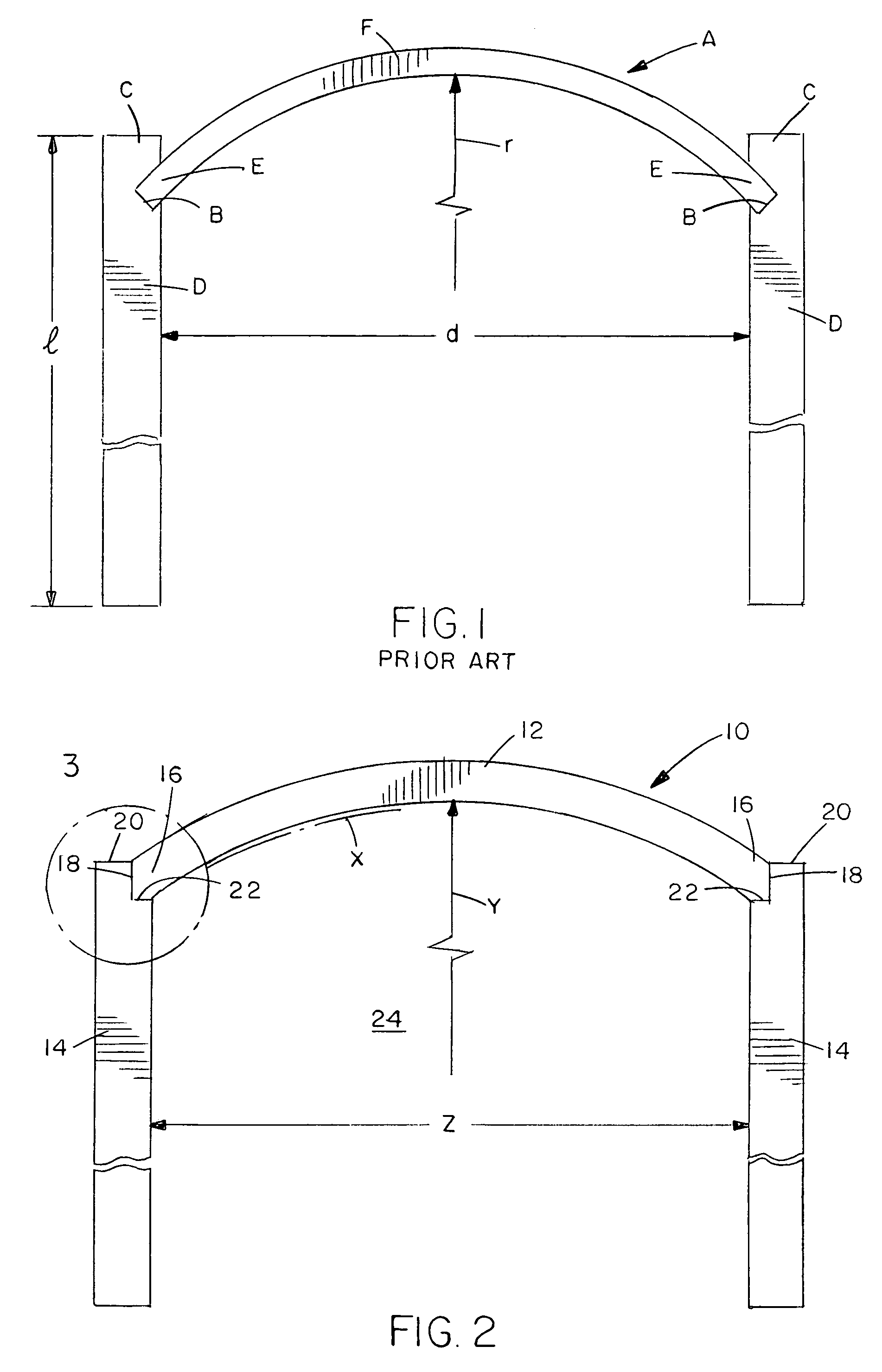
[0010]The present invention provides a standardized arched jamb assembly and construction apparatus and method designed to satisfy the aforementioned need. The arched jamb assembly of the present invention introduces standardization in the sense that cuts made on the opposite ends of an arched jamb member and in the upper end portions of upright jamb members, that form the interfaces there between in the arched jamb assembly, have the same angular configurations, and thus are made standard, irrespective of the curvature of the upper arched jamb member and the horizontal distance between the upright jamb members which is the same as the width of the wall opening defined by the standard arched jamb assembly. The construction apparatus and method of the present invention provide simple and inexpensive tools, techniques and structure for use in constructing the standardized arched jamb assembly.

Problems solved by technology

Heretofore, such variation of arched jamb member curvatures has been accommodated by varying the configurations of the features that support the opposite ends of the arched jamb member which, in turn, accounts for a part of the greater costs of construction of arched jambs over conventional rectangular jambs.
Thus, the upper arched assembly of this prior art arched jamb would add still further costs rather than reduce costs of arched jambs compared to conventional rectangular jambs.

Method used


Image

  • Standardized arched jamb assembly and method
  • Standardized arched jamb assembly and method
  • Standardized arched jamb assembly and method

Examples


Embodiment Construction

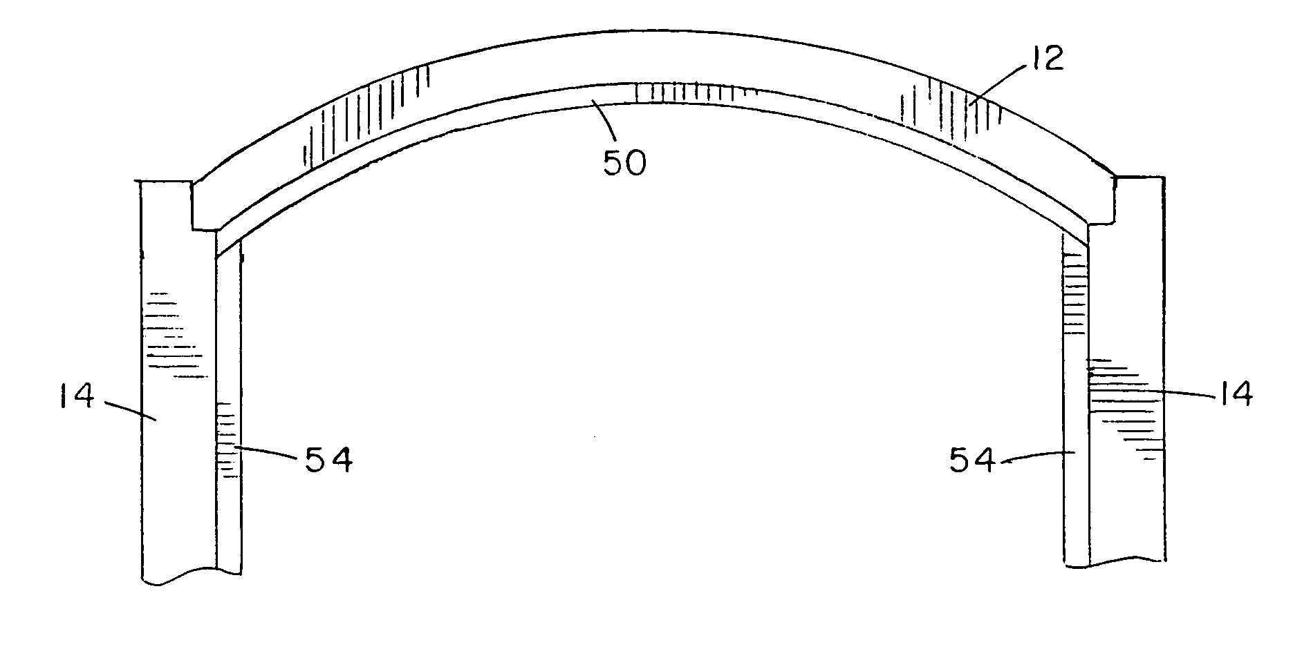
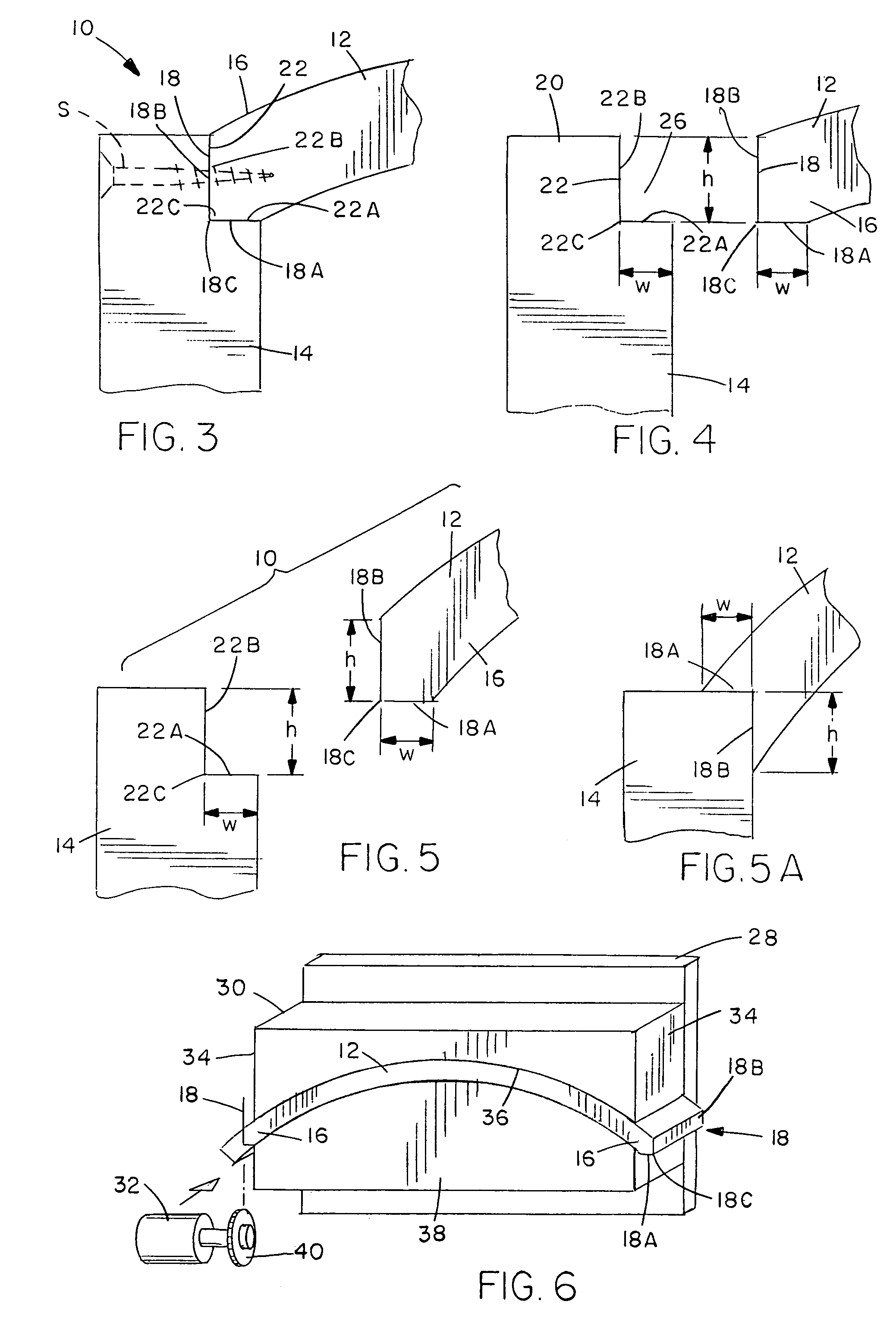
[0037]FIGS. 2 to 5 illustrate an arched jamb assembly according to a first embodiment of the present invention, generally designated 10. The assembly 10 basically includes an arched jamb member 12 and a pair of opposite upright jamb members 14 of wood, laminant, composite, plastic and / or combinations thereof.

[0038]The arched jamb member 12 of the assembly 10 has a pair of opposite ends 16, predetermined curvature “x” and radius of curvature “y”, and a pair of first angled cuts 18 each made on one of the opposite ends 16 of the arched jamb member 12. Each upright jamb member 14 of the assembly 10 has an upper end portion 20 and a second angled cut (or notch) 22 made in the upper end portion 20. The first angled cuts 18 of the arched jamb member 12 respectively meet and interface with the second angled cuts 22 of the upright jamb members 14 so as to assemble the arched jamb member 12 with the upright jamb members 14 to form the arched jamb assembly 10 that defines a wall opening 24 be...


PUM


Abstract

An arched jamb assembly includes an arched jamb member and a pair of opposite upright jamb members with angled cuts made at opposite ends of the arched jamb member and upper end portions of the upright jamb members where the arched jamb member meets and interfaces with the upright jamb members to form the arched jamb assembly. The interfacing angled cuts are two-sided and have substantially the same standard angular configurations, irrespective of variations in the radii of curvature of upper arched jamb members used with upright jamb members to provide wall openings of different widths. An additional stop cut may be formed at opposite ends of the arched jamb member, for bearing against inner stop faces of the upright jamb members.

Description

CROSS REFERENCES TO RELATED APPLICATIONS[0001]This application is a Continuation In Part of application Ser. No. 09 / 954,683 filed Sep. 11, 2001 now U.S. Pat. No. 6,647,673.BACKGROUND OF THE INVENTION[0002]1. Field of the Invention[0003]The present invention generally relates to an arched jamb for providing arched wall openings, such as doorways, windows and the like, and, more particularly, is concerned with a standardized arched jamb assembly and method.[0004]2. Description of the Prior Art[0005]Arched jambs provide arched wall openings, such as doorways, in homes. Arched jambs generally cost more than conventional rectangular jambs but they dramatically enhance the aesthetic appeal and thus the market value of homes.[0006]Prior art arched jambs typically have an upper arched jamb member which defines the top of the arched wall opening and a pair of upright jamb members which define the opposite sides of the wall opening. The upright jamb members have upper end portions which suppo...

Claims


Application Information

Patent Timeline
Patent Type & Authority Patents(United States)
IPC IPC(8): E04B1/32E04C3/42E04C3/46E06B1/00E06B3/984
CPCE04C3/42E04C3/46E06B3/984E06B1/006
Inventor SMERUD, RICHARD J.
Owner SMERUD RICHARD J
Why Eureka
Try Eureka