Fluid dispenser

a dispenser and fluid technology, applied in the field of refillable fluid dispensers, can solve the problems of inability to remove pins from the channel after pin removal, inability to provide industrially reasonable design of vent channels that are incorporated in reservoirs, and difficulty in implementing vent channel design at relatively low cost, so as to eliminate leakage risks and facilitate incorporation and less cost

Active Publication Date: 2014-07-17
APTAR FRANCE SAS
View PDF4 Cites 3 Cited by
  • Summary
  • Abstract
  • Description
  • Claims
  • Application Information

AI Technical Summary

Benefits of technology

[0019]The spirit of the invention stems from it being easier and less costly to incorporate the vent channel in the reservoir. However, molding as a single part requires the vent channel to be of a certain section and of a certain shape, and this could generate risks of leakage. In order to eliminate the risks of leakage, the vent channel is extended by a vent passage of section that is smaller, which vent passage is formed by a stationary element that is fitted on the bottom wall of the reservoir. Ingeniously, the stationary element also forms the seat of the filling valve.

Problems solved by technology

It can easily be understood that that vent-channel design is difficult to implement at relatively low cost.
In this respect, the design of the vent channel that is incorporated in the reservoir cannot be provided in industrial manner and at moderate cost.
Such a pin could not be removed from the channel after molding as a result of its long length and its extreme fineness.

Method used


Image

  • Fluid dispenser
  • Fluid dispenser
  • Fluid dispenser

Examples


Embodiment Construction

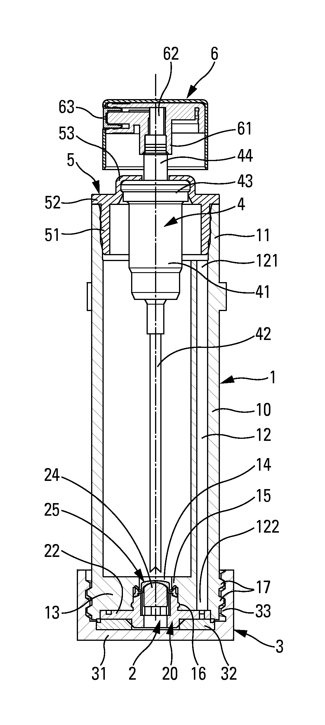
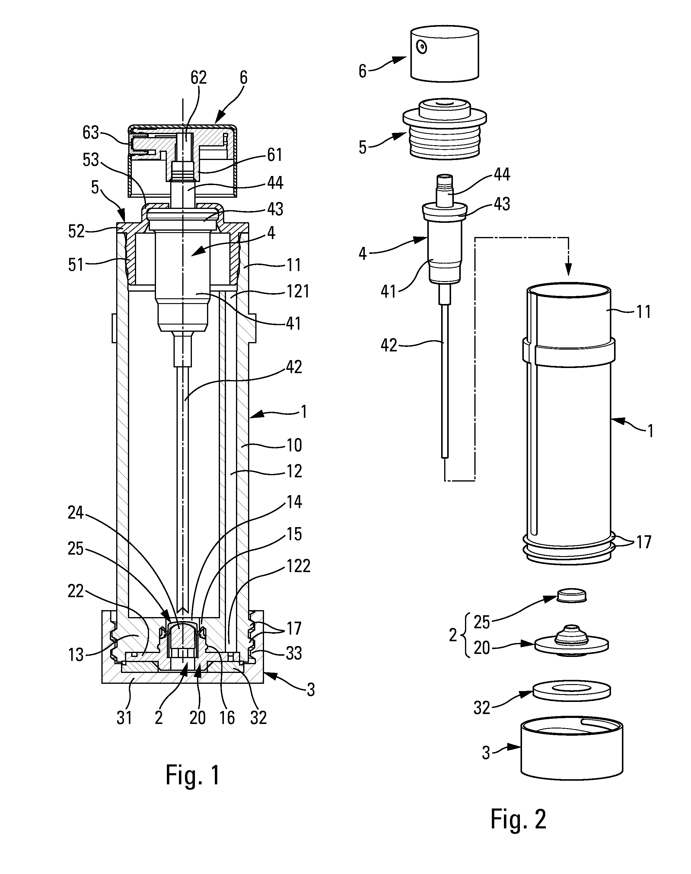
[0030]Reference is made firstly to FIGS. 1 and 2 in order to describe, in overall manner, the structure of a refillable fluid dispenser in a non-limiting embodiment of the invention. The dispenser comprises the following component elements, namely a fluid reservoir 1, a filling valve 2, an optional removable cap 3, a dispenser member 4, a fastener ring 5, and a pusher 6.

[0031]By way of example, the dispenser member 4 may be a pump comprising a pump body 41 that is provided at its bottom end with a dip tube 42 and at its top end with a holding collar 43. The pump also comprises an actuator rod 44 that is axially movable down and up inside the body 41, in such a manner as to cause the volume of a pump chamber (not shown) to vary. In an entirely conventional manner, the pump 4 is provided with an inlet valve and with an outlet valve at opposite ends of the pump chamber, such that the fluid may penetrate into the pump chamber through the dip tube 42 and the open inlet valve, and leave t...


PUM


Abstract

A refillable fluid dispenser comprising:
    • a fluid reservoir (1) defining a neck (11) and a bottom wall (13);
    • a filling valve (2);
    • a dispenser member (4), such as a pump;
    • a pusher (6) that is mounted on the dispenser member (4); and
    • a vent channel (12) that extends along the fluid reservoir (1) and that is made integrally with the fluid reservoir (1);
    • the dispenser being characterized in that it includes a stationary element (20) that is mounted on the bottom wall (13) of the fluid reservoir (1), the stationary element (20) forming a vent passage (221, 222) that connects the outlet of the vent channel (12) to the outside.

Description

CROSS REFERENCE TO RELATED APPLICATION[0001]This application claims the benefit under 35 U.S.C. §119(e) of pending U.S. provisional patent application Ser. No. 61 / 759,794, filed Feb. 1, 2013, and priority under 35 U.S.C. §119(a)-(d) of French patent application No. FR-13 50273, filed Jan. 11, 2013.TECHNICAL FIELD[0002]The present invention relates to a refillable fluid dispenser comprising:[0003]a fluid reservoir defining a neck and a bottom wall;[0004]a filling valve that is mounted in the bottom wall, the filling valve including a movable member and a stationary element forming a valve seat for the movable member;[0005]a dispenser member, such as a pump, that is mounted on the reservoir so as to take the fluid;[0006]a pusher that is mounted on the dispenser member; and[0007]a vent channel that extends along the fluid reservoir so as to put the fluid reservoir into communication with the outside, the vent channel defining an inlet in the proximity of the neck, and an outlet that op...

Claims


Application Information

Patent Timeline
Patent Type & Authority Applications(United States)
IPC IPC(8): B05B11/00
CPCB05B11/3001B05B11/0056B05B11/1001
Inventor BERTIN, ROMAINLESAGE, PIERRE-ALAIN
Owner APTAR FRANCE SAS
Why Eureka
Try Eureka