Methods for molding interbody devices in situ

a technology of interbody devices and fusion devices, which is applied in the field of can solve the problems of most costly health problems in society, back pain and spine pathology, and great suffering of victims, and achieve the effect of reducing the cost of fusion devices

Inactive Publication Date: 2009-01-01
NADER REMI +1
View PDF3 Cites 2 Cited by
  • Summary
  • Abstract
  • Description
  • Claims
  • Application Information

AI Technical Summary

Benefits of technology

[0024]In the instant process, a small portion of polymethylmethacrylate is used to create an interbody device. This process significantly reduces the cost of the fusion device to merely a fraction of the cost of prefabricated spacers.

Problems solved by technology

One of the most costly health problems in society involves back pain and pathology of the spine.
These problems can affect individuals of all ages and can result in great suffering to victims.
Such changes can cause painful excessive motion, or collapse of a motion segment resulting in the contraction of the spinal canal and compressing the neural structures, causing debilitating pain, paralysis, or both, which in turn can result in nerve root compression or spinal stenosis.
However, diseased, degenerated, displaced, or otherwise damaged discs (e.g., herniated or ruptured discs) manifest numerous undesirable symptoms, including nerve damage, pain, spinal instability, numbness and decreased mobility.
There is always a risk in opening a second surgical site to obtain the implant, which can lead to infection or pain for the patient, and the site of the implant is weakened by the removal of bony material.
The bone implant may not be perfectly shaped and placed, leading to slippage or absorption of the implant or failure of the implant to fuse with the vertebrae.
In these cases, while there is the benefit of not requiring a second surgical site as a possible source of infection or pain, there is increased likelihood of graft rejection and a risk of transmitting communicable diseases.
However, when PMMA in liquid form was poured into the disk space and allowed to harden, to form a stand alone device, the device was demonstrated not to promote the most optimal fusion based on radiographic result as compared with discectomy alone (Clinical Neurosurgery 52:197).
However, these prefabricated spacers are often exceedingly and unnecessarily expensive.

Method used


Image

  • Methods for molding interbody devices in situ
  • Methods for molding interbody devices in situ
  • Methods for molding interbody devices in situ

Examples


Embodiment Construction

[0030]For purposes of the present application, CIMD can be used interchangeably with IMD. It is clear that the method and device are not limited to cervical procedures, but can be used for all relevant orthopedic and neurosurgical procedures.

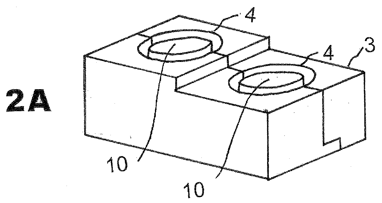
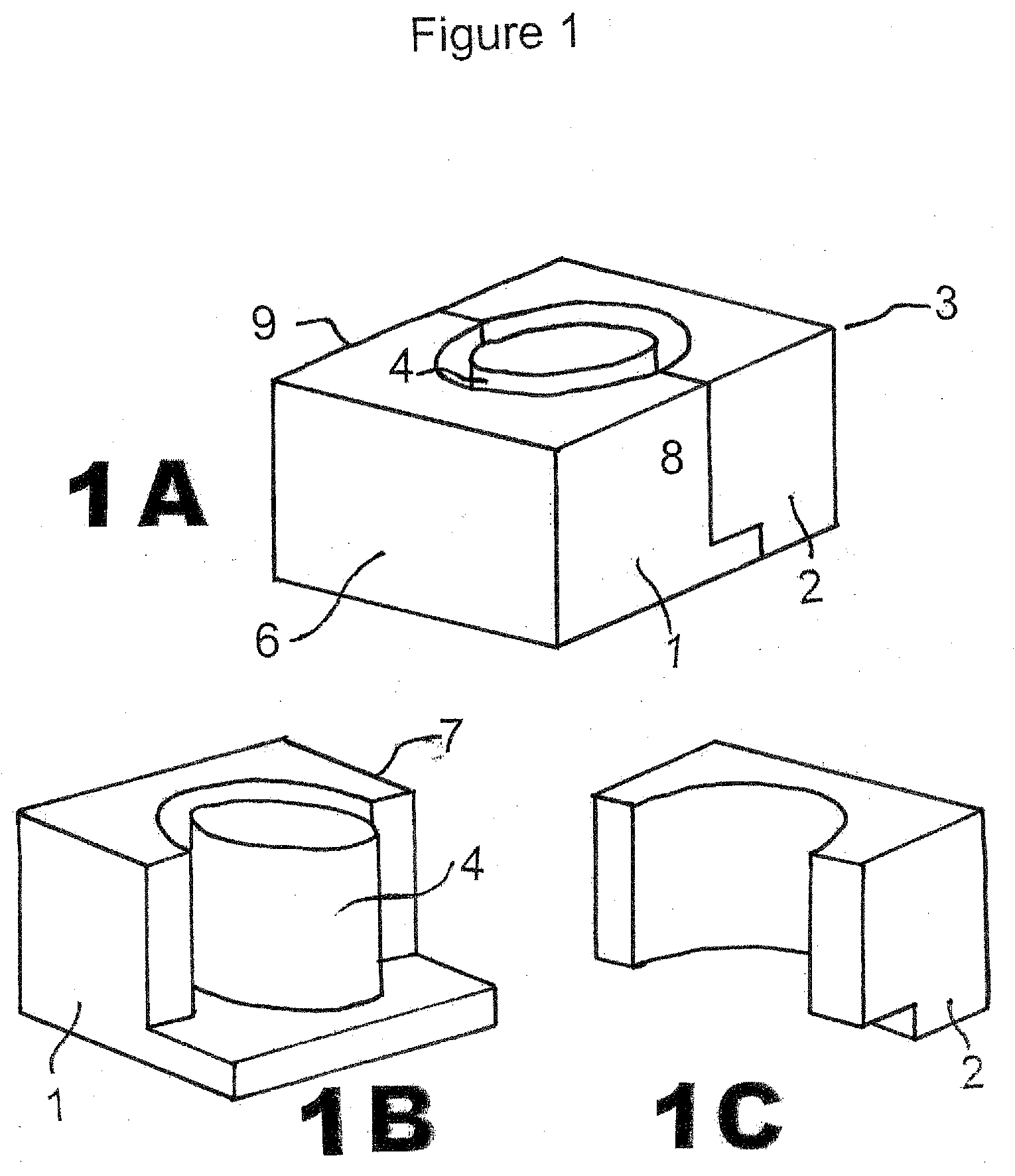
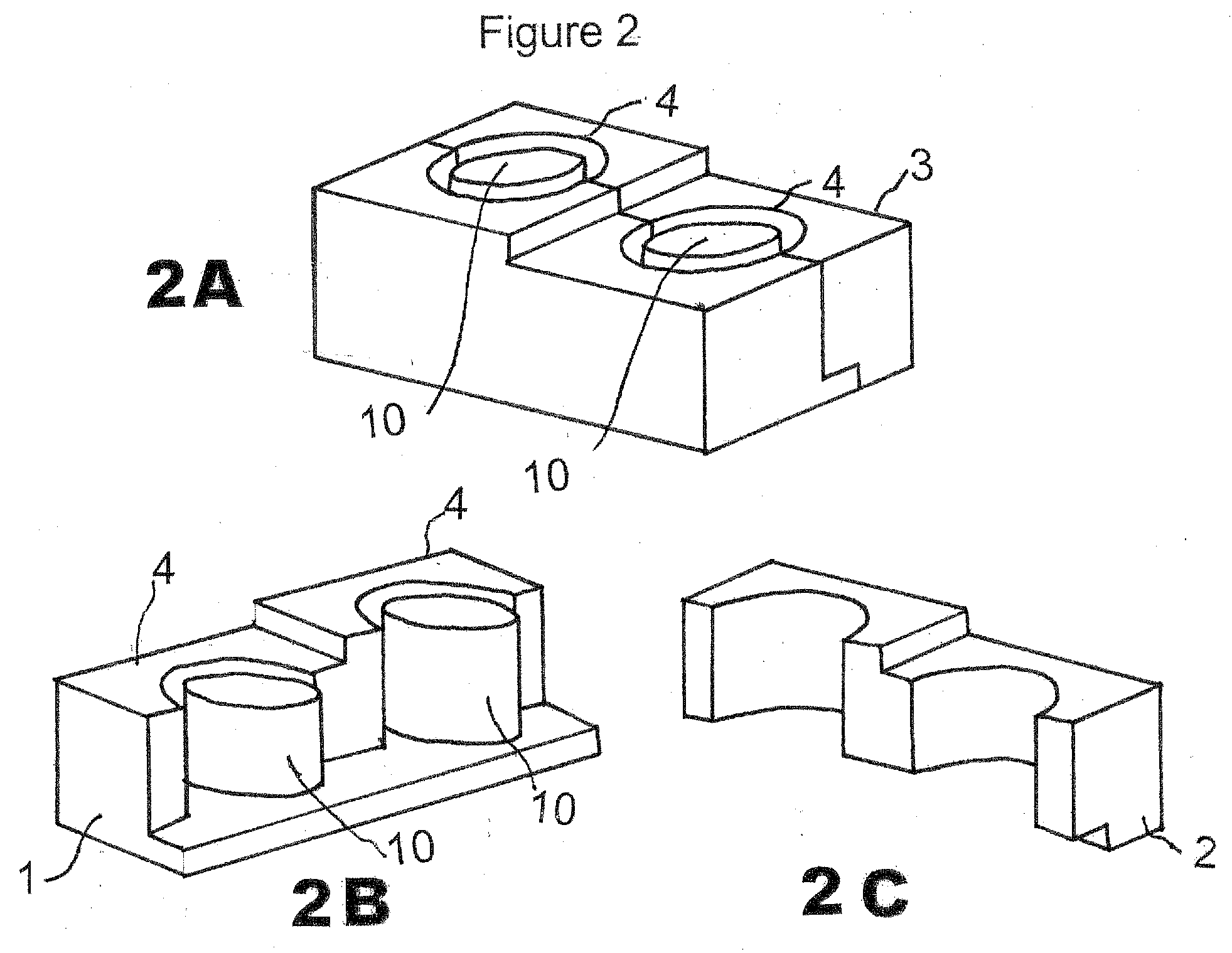
[0031]The CIMD 3 is composed of two parts 1, 2 which, when combined together as shown in FIG. 1A, form a stand-alone mold which can be separated for release after hardening of the interbody spacer created in situ after separation from its inner cylinder mold 4. Generally, the CIMD has a pair of flat side faces and inner faces formed of half cavities.

[0032]FIG. 1A shows the CIMD 3 closed (parts 1 and 2 combined together by apposition). FIGS. 1B and 1C demonstrate the CIMD 3 open as part 1 (FIG. 1B) and part 2 (FIG. 1C) are separated. A form 10 is in the center of the closed CIMD so that the spacer formed is open on the inside.

[0033]Typically, the CIMD 3 when assembled includes a top wall 4, a bottom wall 5, shown in FIG. 3B, a first end wall 6, a...


PUM

PropertyMeasurementUnit
sizesaaaaaaaaaa
movementaaaaaaaaaa
biologically compatibleaaaaaaaaaa

Abstract

A method is provided for producing and inserting a cervical interbody mold device (CIMD). The CIMD produces an interbody device that is formed in situ and that possesses suitable strength and biocompatibility so as to provide sufficient vertebral support while providing optimal ease of use and insertion for the surgeon.

Description

FIELD OF THE INVENTION[0001]One of the most costly health problems in society involves back pain and pathology of the spine. These problems can affect individuals of all ages and can result in great suffering to victims. Back pain can be caused by several factors, such as congenital deformities, traumatic injuries, degenerative changes to the spine, and the like. Such changes can cause painful excessive motion, or collapse of a motion segment resulting in the contraction of the spinal canal and compressing the neural structures, causing debilitating pain, paralysis, or both, which in turn can result in nerve root compression or spinal stenosis.[0002]Intervertebral discs, disposed between endplates of adjacent vertebrae, both stabilize the spine and cushion vertebral bodies. However, diseased, degenerated, displaced, or otherwise damaged discs (e.g., herniated or ruptured discs) manifest numerous undesirable symptoms, including nerve damage, pain, spinal instability, numbness and dec...

Claims


Application Information

Patent Timeline
Patent Type & Authority Applications(United States)
IPC IPC(8): B29B9/00A61B17/58
CPCA61F2/30942A61F2/4465A61F2002/2835A61F2310/00353A61F2002/30957A61F2230/0069A61F2002/30235
Inventor NADER, REMIMILLER, JIMMY D.
Owner NADER REMI
Why Eureka
Try Eureka