Lifting facility

A technology of equipment and lifting devices, which is applied in the direction of conveyor objects, supporting frames, transportation and packaging, etc., can solve problems such as equipment collision damage, lifting asynchronous, lifting equipment can not meet the demand, etc., to improve the rotation accuracy , to eliminate the effect of butt joint gap

Pending Publication Date: 2019-02-05
KOCEL INTELLIGENT FOUNDRY IND INNOVATION CENT CO LTD
View PDF7 Cites 2 Cited by
  • Summary
  • Abstract
  • Description
  • Claims
  • Application Information

AI Technical Summary

Problems solved by technology

[0002] At present, the company uses hood-type microwave drying equipment to heat and cure the sand cores in the work box by microwave. The work box is huge and heavy, but the existing lifting work box device has asynchronous rolling, asynchronous lifting, and precision. The poor problem, the unsynchronized rolling caused the working box to be stuck and stuck during the rolling transfer process, and the unsynchronized lifting caused the docking to be incomplete and there was a gap, which caused microwave leakage. Because they are all heavy equipment, poor precision caused The equipment is severely damaged by extrusion or collision. It can be seen that the existing lifting equipment cannot meet the demand

Method used


Image

  • Lifting facility
  • Lifting facility
  • Lifting facility

Examples


Embodiment Construction

[0020] With reference to the drawings of the present invention, a technical solution of the embodiment of the invention will be further elaborated.

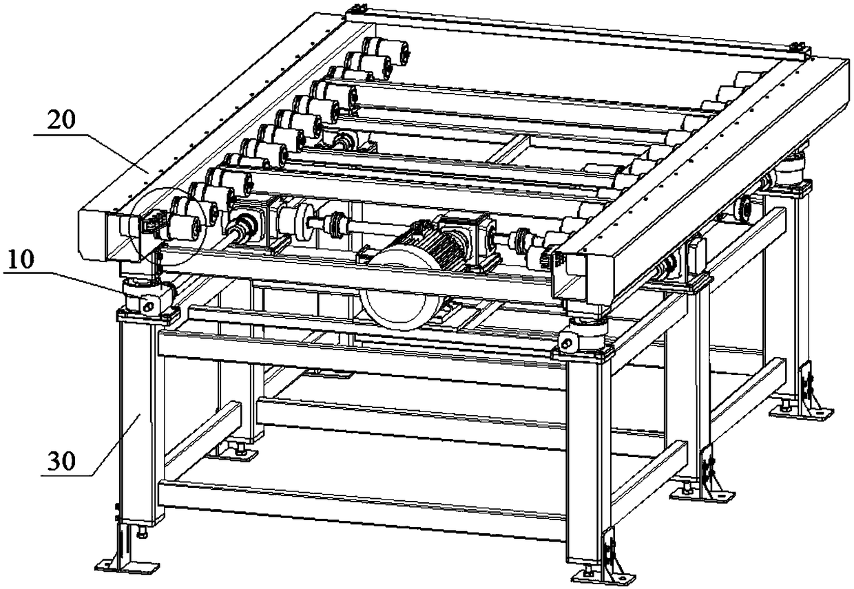
[0021] Reference attached figure 1 As shown, a lifting device includes a lifting device 10, a roller table device 20, and a fixing frame 30. The upper part of the lifting device 10 arranged on the fixing frame 30 is provided with a roller table device 20, and the lifting device 10 is used for lifting Lift roller device 20.

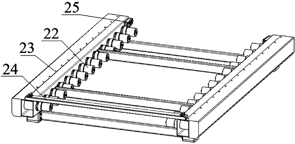
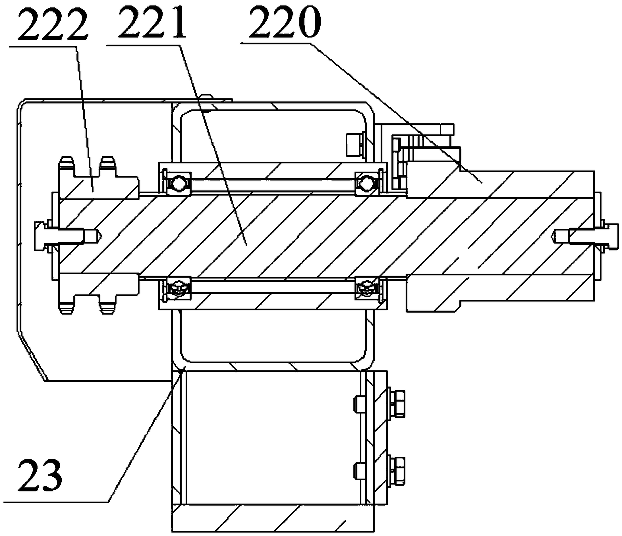
[0022] Reference attached figure 2 As shown, the roller table device 20 includes a roller table driving device 21, a roller table group 22, a roller table frame 23, a limiting device 24, and a guide device 25. The roller table group 22 includes a wheel body 220, a roller shaft 221, and a roller sprocket. 222. Chain, refer to attachment image 3 As shown, both sides of the upper part of the roller frame 23 are respectively mounted with a row of roller shafts 221, the roller shaft 221 on the opposite side of the tw...


PUM


Abstract

The invention provides a lifting facility. The lifting facility comprises a lifting device, a roller bed device and a fixing frame. The roller bed device is arranged on the upper portion of the lifting device which is arranged on the fixing frame. The lifting device is used for lifting the roller bed device. Two rows of roller shafts are separately mounted on the two sides of the upper portion ofa roller bed frame through bearings. Wheel bodies are mounted on the opposite sides of the two rows of roller shafts, and roller chain wheels are mounted on the outer sides of the roller shafts. Eachroller chain wheel is formed by two circles of teeth arranged side by side. Every two adjacent roller chain wheels are connected through a chain. A driving motor drives a rotary shaft to rotate through a transmission device. Two chain wheels are separately arranged at the two ends of the rotary shaft. The two chain wheels are in linkage with the corresponding roller chain wheels in the two rows through the chains, then the driving motor drives rollers on the two sides to synchronously rotate, and a roller bed synchronously rolls at high precision and is synchronously lifted at high precision,so that tight butt joint of a workbox and a microwave device is completed, and microwave leakage is avoided.

Description

Technical field [0001] The invention relates to the field of microwave drying equipment, in particular to a lifting equipment. Background technique [0002] The company currently uses hood-type microwave drying equipment for microwave heating and curing of the sand core in the working box. The working box is huge and heavy, but the existing lifting working box device has rolling asynchronous, lifting asynchronous, and precision Poor problem, the unsynchronized rolling causes the work box to shift and jam during the rolling transfer process, and the unsynchronized lifting leads to the incomplete docking gap and the problem of microwave leakage, because they are heavy equipment, and the accuracy is poor. The equipment is severely damaged by squeezing or collision. It can be seen that the existing lifting equipment cannot meet the demand. Summary of the invention [0003] In view of the shortcomings of the prior art, the present invention provides a lifting device. One aspect of the...

Claims


Application Information

Patent Timeline
Patent Type & Authority Applications(China)
IPC IPC(8): B65G13/07B65G47/22B65G47/24B65G13/12B65G41/00
CPCB65G13/07B65G13/12B65G41/003B65G47/22B65G47/24
Inventor 侯奇林王永恩王博周鹏举
Owner KOCEL INTELLIGENT FOUNDRY IND INNOVATION CENT CO LTD
Why Eureka
Try Eureka