
Magnetoelectric control of superparamagnetism

Active Publication Date: 2014-07-17
RGT UNIV OF CALIFORNIA
View PDF1 Cites 5 Cited by
  • Summary
  • Abstract
  • Description
  • Claims
  • Application Information

AI Technical Summary

Benefits of technology

The patent describes a new system that can switch between a magnetic state and an electric state using an electric field. This can be done using a special material made of two phases - one magnetic and one electric. The electric field causes the magnetic material to behave like a ferromagnet. This system is important because it allows for the use of electricity to control magnetism, which could lead to new electromagnetic devices.

Problems solved by technology

Strain transfer from the substrate to the magnetic component of the system results in perturbation of the magnetization of the system.

Method used


Image

  • Magnetoelectric control of superparamagnetism
  • Magnetoelectric control of superparamagnetism
  • Magnetoelectric control of superparamagnetism

Examples


Embodiment Construction

[0024]In the embodiments disclosed below, superparamagnetism is used to intrinsically control the net magnetization of the magnetoelectric system of the present invention. The superparamagnetism occurs in nanoscale ferromagnetic crystals when the ambient thermal energy is larger than the magnetic anisotropy, resulting in a zero magnetization state. While the systems and methods of the present invention are primarily embodied below in one combination of materials (e.g. Ni nanocrystals on a piezoelectric PMN-PT substrate) it is appreciated that the principles of the present invention may be broadly applied to any class of small magnetic nanostructures strain or charge coupled to any ferroelectrics / piezoelectrics.

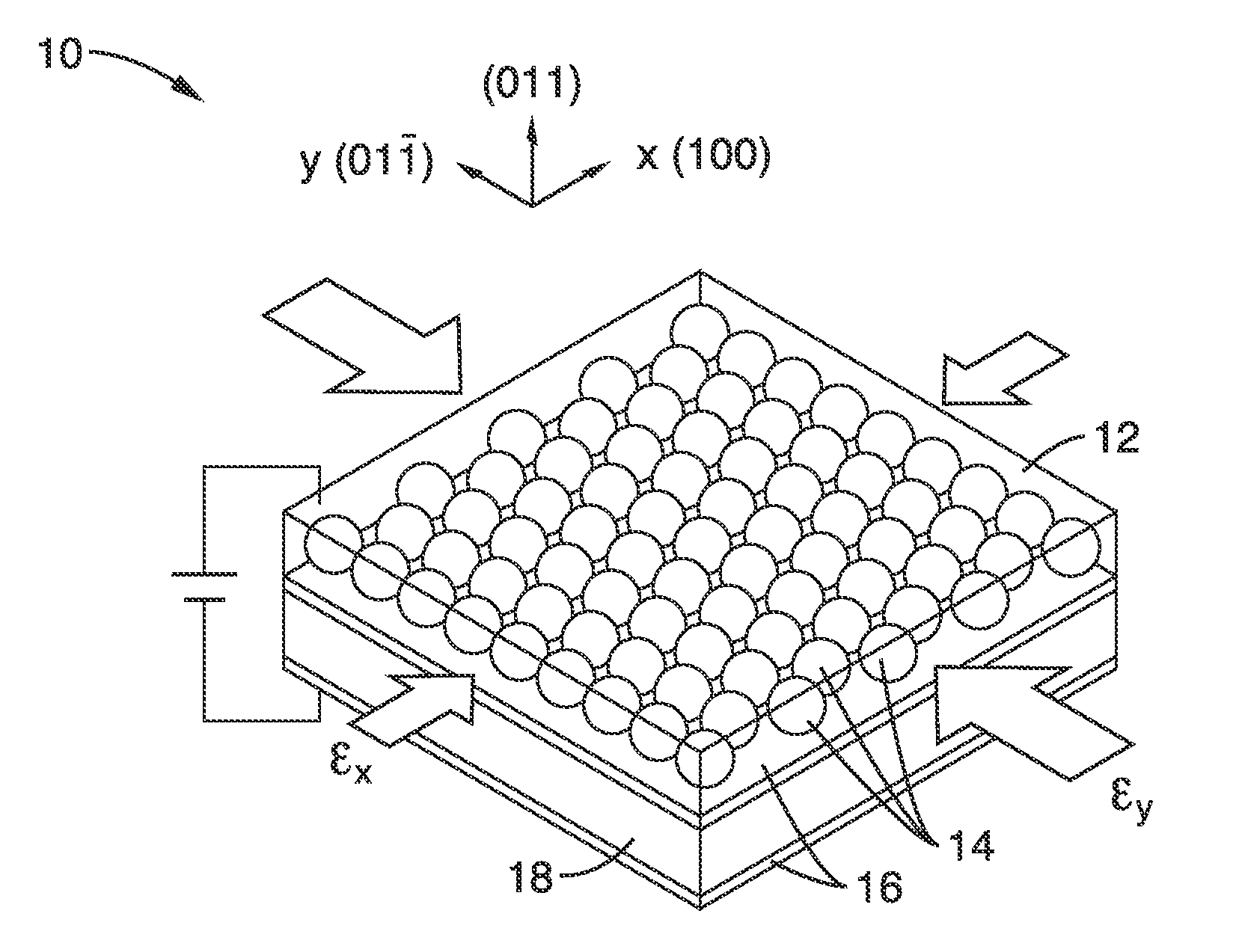
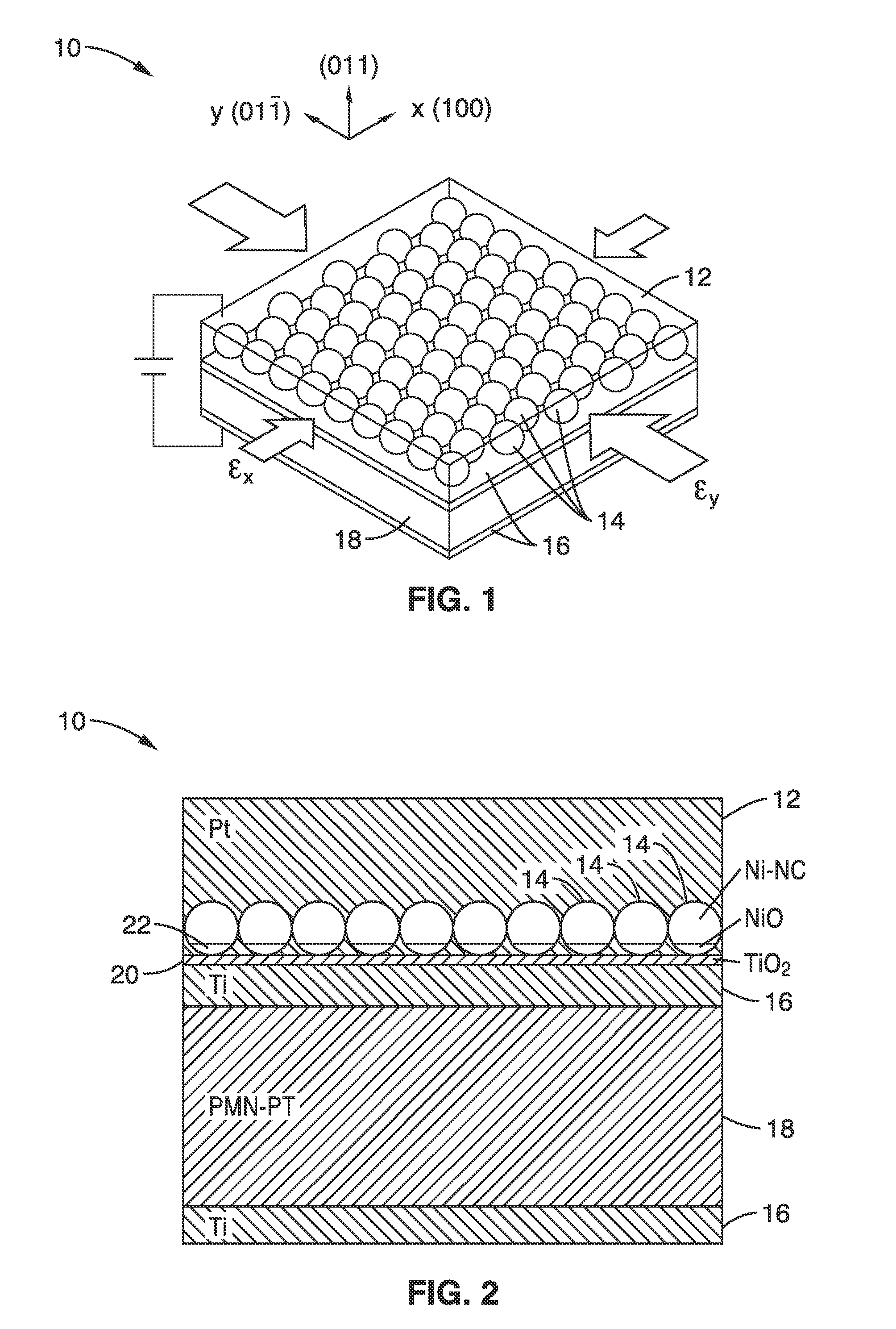
[0025]FIG. 1 shows a perspective schematic diagram of a magnetoelectric composite device 10 in accordance with the present invention composed of a free (i.e. switchable) layer 12 of ferromagnetic nanocrystals mechanically coupled to a (011) [Pb(Mg1 / 3Nb2 / 3O3](1-x)—[PbTiO3]x (PM...


PUM


Abstract

A magnetoelectric composite device having a free (i.e. switchable) layer of ferromagnetic nanocrystals mechanically coupled a ferroelectric single crystal substrate is presented, wherein application of an electrical field on the composite switches the magnetic state of the switchable layer from a superparamagnetic state having no overall net magnetization to a substantially single-domain ferromagnetic state.

Description

CROSS-REFERENCE TO RELATED APPLICATIONS[0001]This application claims the benefit of, and priority to, U.S. provisional patent application Ser. No. 61 / 752,110 filed on Jan. 14, 2013, incorporated herein by reference in its entirety.STATEMENT REGARDING FEDERALLY SPONSORED RESEARCH OR DEVELOPMENT[0002]This invention was made with Government support under Grant No. FA9550-09-1-0677 awarded by the Air Force Office of Scientific Research (AFOSR), and Grant No. CHE-1112569 awarded by the National Science Foundation (NSF). The Government has certain rights in this invention.INCORPORATION-BY-REFERENCE OF COMPUTER PROGRAM APPENDIX[0003]Not ApplicableNOTICE OF MATERIAL SUBJECT TO COPYRIGHT PROTECTION[0004]A portion of the material in this patent document is subject to copyright protection under the copyright laws of the United States and of other countries. The owner of the copyright rights has no objection to the facsimile reproduction by anyone of the patent document or the patent disclosure...

Claims


Application Information

Patent Timeline
IPC IPC(8): H01F7/06
CPCH01F7/064H01F1/0063H01F1/0036H01F1/0018
Inventor TOLBERT, SARAH H.CARMAN, GREGORY P.KELLER, SCOTTSCHELHAS, LAURAKIM, HYUNGSUKHOCKEL, JOSHUA
Owner RGT UNIV OF CALIFORNIA
Learn More