Stereo assist with rolling shutters

a technology of rolling shutters and assist devices, applied in the field of camera imaging systems, can solve problems such as difficulty in direct determination of distance to a target object, stereo systems may experience difficulties, and difficulty in imaging objects at longer distances from the vehicl

Active Publication Date: 2014-07-17
MOBILEYE VISION TECH LTD
View PDF0 Cites 192 Cited by
  • Summary
  • Abstract
  • Description
  • Claims
  • Application Information

AI Technical Summary

Problems solved by technology

Because the images in these types of systems are captured from a single point of view, direct determination of distance to a target object can be challenging.
However, such stereo systems may experience difficulties during adverse weather conditions or where cluttered scenes exist.
Additionally, these systems may have difficulty imaging objects at longer distances from the vehicle.
Such a rolling shutter may introduce complications in stereo image processing, especially in asymmetric stereo applications that use cameras having different fields of view.
Such a lack of synchronization may introduce difficulties in determining a correspondence of image points in a first image from the wide FOV camera with image points in a second image from the narrow FOV camera, which can lead to significant inaccuracies object distance measurements.

Method used


Image

  • Stereo assist with rolling shutters
  • Stereo assist with rolling shutters
  • Stereo assist with rolling shutters

Examples


Embodiment Construction

[0036]The following detailed description refers to the accompanying drawings. Wherever possible, the same reference numbers are used in the drawings and the following description to refer to the same or similar parts. While several illustrative embodiments are described herein, modifications, adaptations and other implementations are possible. For example, substitutions, additions or modifications may be made to the components illustrated in the drawings, and the illustrative methods described herein may be modified by substituting, reordering, removing, or adding steps to the disclosed methods. Accordingly, the following detailed description is not limiting of the disclosed embodiments. Instead, the proper scope is defined by the appended claims.

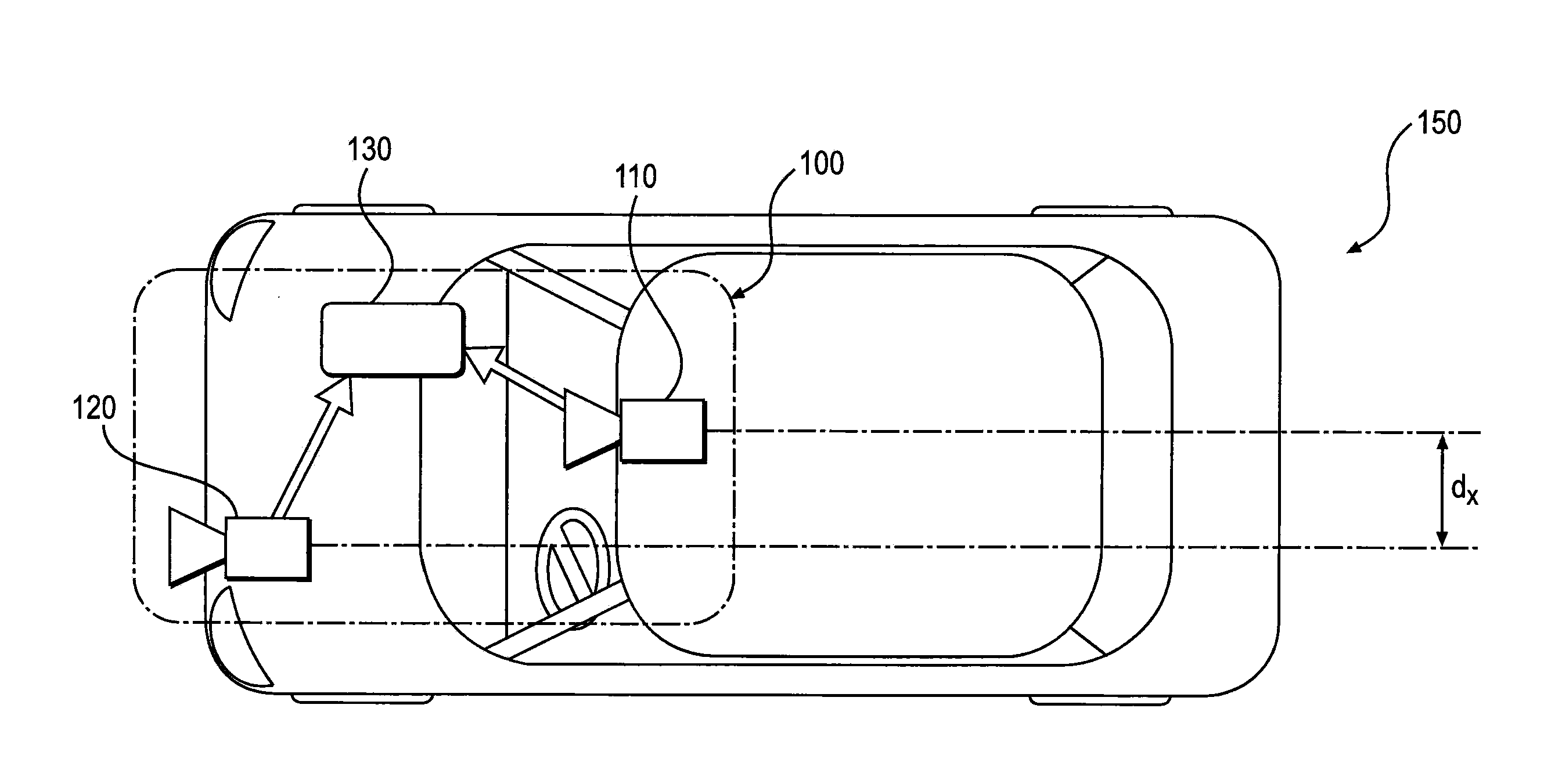
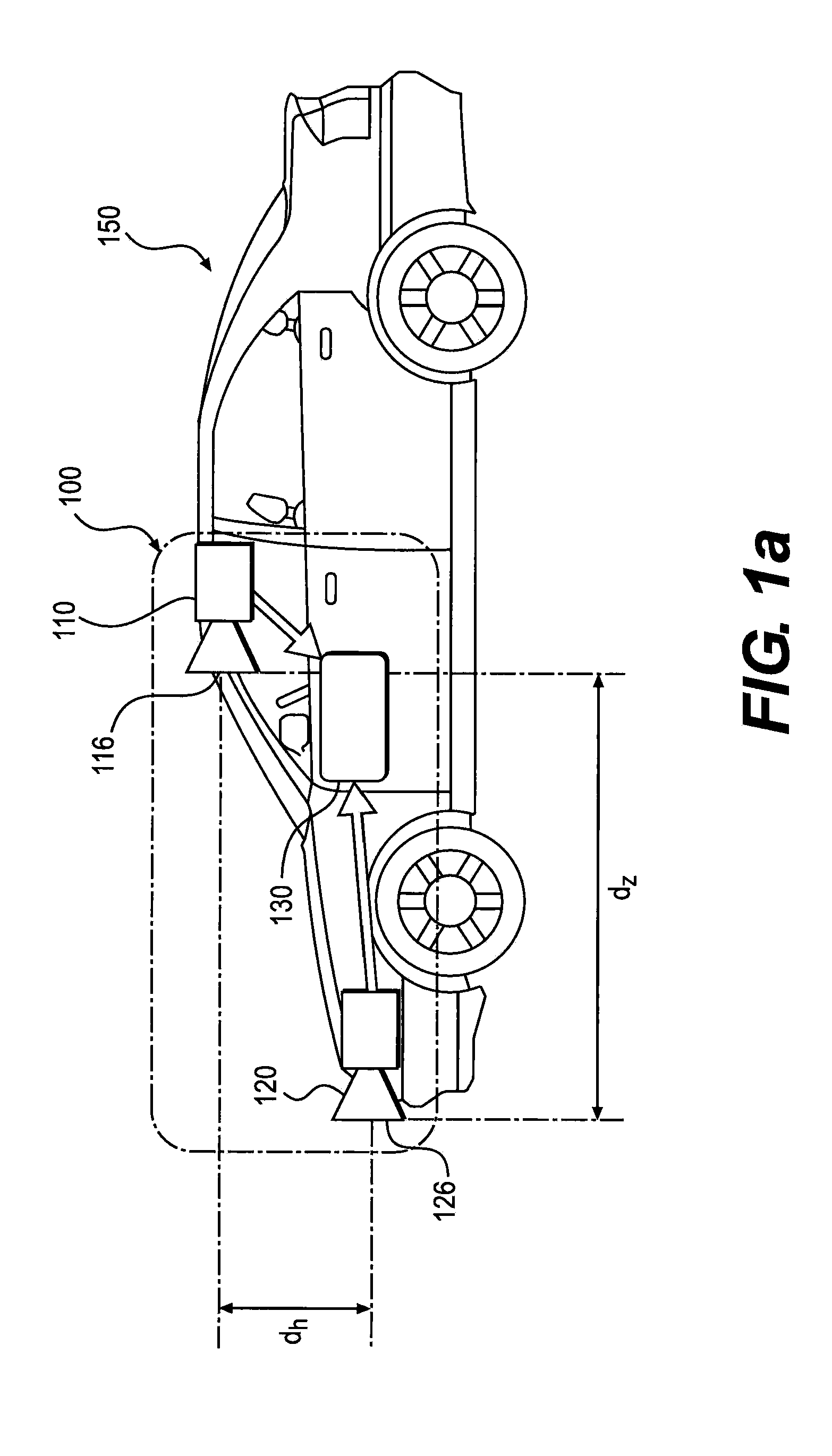
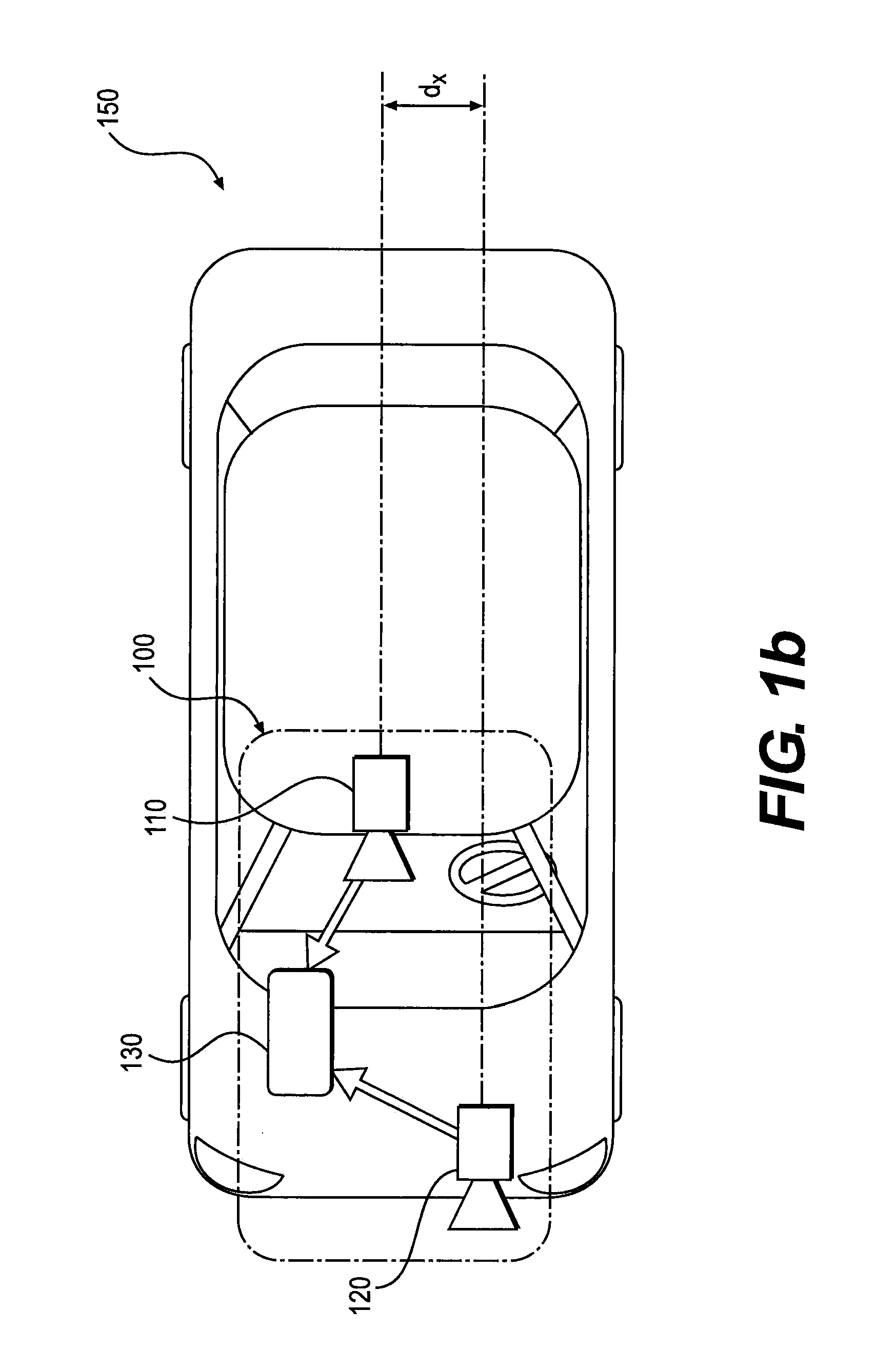
[0037]Referring to the accompanying drawings, FIG. 1a is a diagrammatic, side view representation of an exemplary vehicle imaging system consistent with the presently disclosed. FIG. 1b is diagrammatic, top view illustration of the embodime...


PUM


Abstract

An imaging system for a vehicle may include a first image capture device having a first field of view and configured to acquire a first image relative to a scene associated with the vehicle, the first image being acquired as a first series of image scan lines captured using a rolling shutter. The imaging system may also include a second image capture device having a second field of view different from the first field of view and that at least partially overlaps the first field of view, the second image capture device being configured to acquire a second image relative to the scene associated with the vehicle, the second image being acquired as a second series of image scan lines captured using a rolling shutter. As a result of overlap between the first field of view and the second field of view, a first overlap portion of the first image corresponds with a second overlap portion of the second image. The first image capture device has a first scan rate associated with acquisition of the first series of image scan lines that is different from a second scan rate associated with acquisition of the second series of image scan lines, such that the first image capture device acquires the first overlap portion of the first image over a period of time during which the second overlap portion of the second image is acquired.

Description

[0001]This application claims priority under 35 U.S.C. §119 to U.S. Provisional Application No. 61 / 752,515, filed Jan. 15, 2013, and U.S. Provisional Application No. 61 / 761,724, filed Feb. 7, 2013. Each aforementioned application is incorporated herein by reference in its entirety.BACKGROUND[0002]I. Technical Field[0003]The present disclosure relates generally to camera imaging systems and more specifically to devices and techniques for capturing images in a rolling shutter, stereo image acquisition system that may be included on a vehicle.[0004]II. Background Information[0005]Camera based driver assistance systems for use in vehicles may include monocular object detection systems that rely primarily on a single camera to collect images. Because the images in these types of systems are captured from a single point of view, direct determination of distance to a target object can be challenging. Therefore, monocular object detection systems may rely upon estimation techniques to indir...

Claims


Application Information

Patent Timeline
Patent Type & Authority Applications(United States)
IPC IPC(8): H04N13/02
CPCH04N13/0282H04N13/25H04N13/282H04N13/296G06V20/56H04N23/60H04N23/90H04N25/531H04N23/69B60R1/00H04N5/04B60R2300/105B60R2300/303B60R2300/8093
Inventor STEIN, GIDEONBELMAN, EFIM
Owner MOBILEYE VISION TECH LTD
Why Eureka
Try Eureka