
Reversible USB connector

a usb connector and polarizing technology, applied in the direction of coupling device details, coupling contact members, coupling device connections, etc., can solve the problems of confusing users, markings are not always used by users, and users are difficult to determine when a polarized plug is used

Inactive Publication Date: 2014-07-24
APPLE INC
View PDF11 Cites 72 Cited by
  • Summary
  • Abstract
  • Description
  • Claims
  • Application Information

AI Technical Summary

Benefits of technology

The present invention relates to improvements in input / output electrical connectors, such as USB connectors, that can prevent incorrect insertion of plug connectors and damage to the connectors and user frustration. The technical effect of the invention is to provide connectors that do not require a specific orientation for proper functioning, but instead have features that indicate the proper orientation for insertion. This makes it easier for users to ensure that the connectors are properly oriented and can be easily identified. The invention also includes simplified methods for manufacturing the connectors and markings that indicate the orientation of the connectors, which can be consistent and applied consistently across manufacturers.

Problems solved by technology

It is sometimes difficult for users to determine when a polarized plug connector, such as a USB plug connector, is oriented in the correct orientation for insertion into a corresponding receptacle connector.
However, these marking are not always utilized by users and / or can be confusing to some users.
In some cases, these markings are not helpful because the markings cannot be easily viewed due to the location of the receptacle connector, lighting conditions, or other reasons.
Even when visible, these markings may still be unhelpful because not all manufacturers apply these markings in a consistent fashion.
Consequently, users may incorrectly insert a plug connector into a corresponding receptacle connector, which may potentially result in damage to the connectors and / or user frustration.

Method used


Image

  • Reversible USB connector
  • Reversible USB connector
  • Reversible USB connector

Examples


Embodiment Construction

[0030]The present invention will now be described in detail with reference to certain embodiments thereof as illustrated in the accompanying drawings. In the following description, numerous specific details are set forth in order to provide a thorough understanding of the present invention. It will be apparent, however, to one skilled in the art, that the present invention may be practiced without some or all of these specific details. In other instances, well known details have not been described in detail in order not to unnecessarily obscure the present invention.

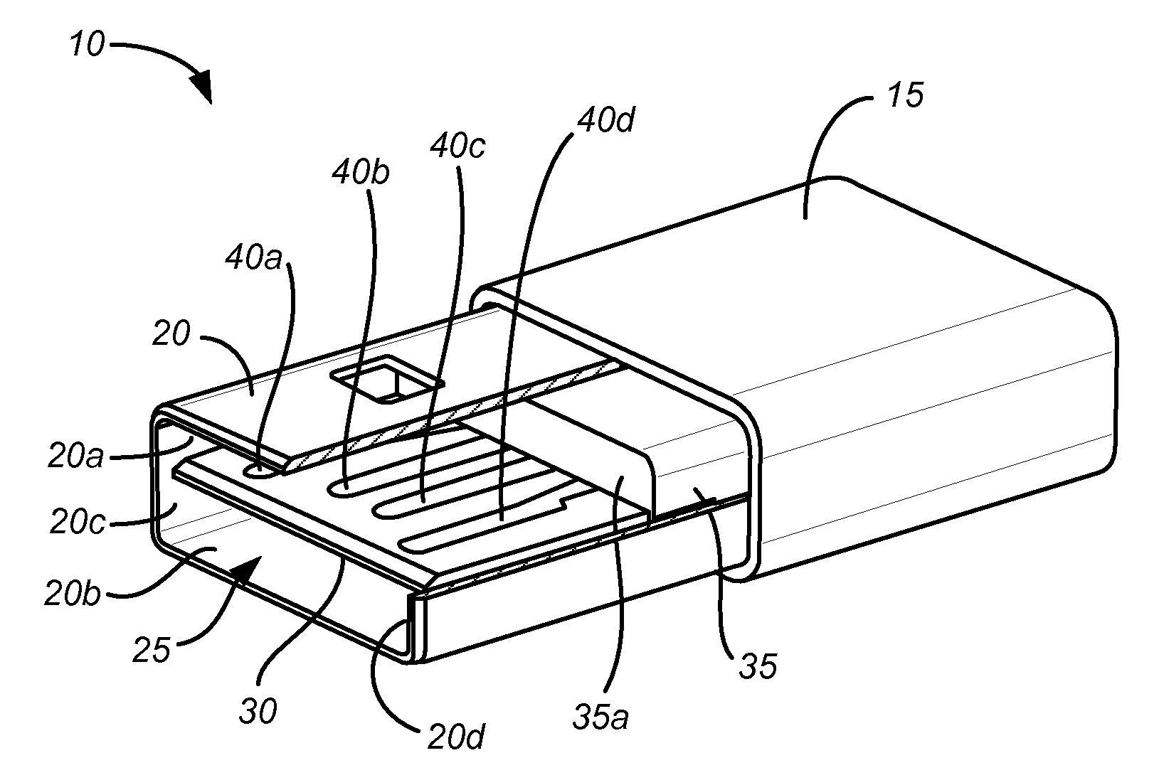
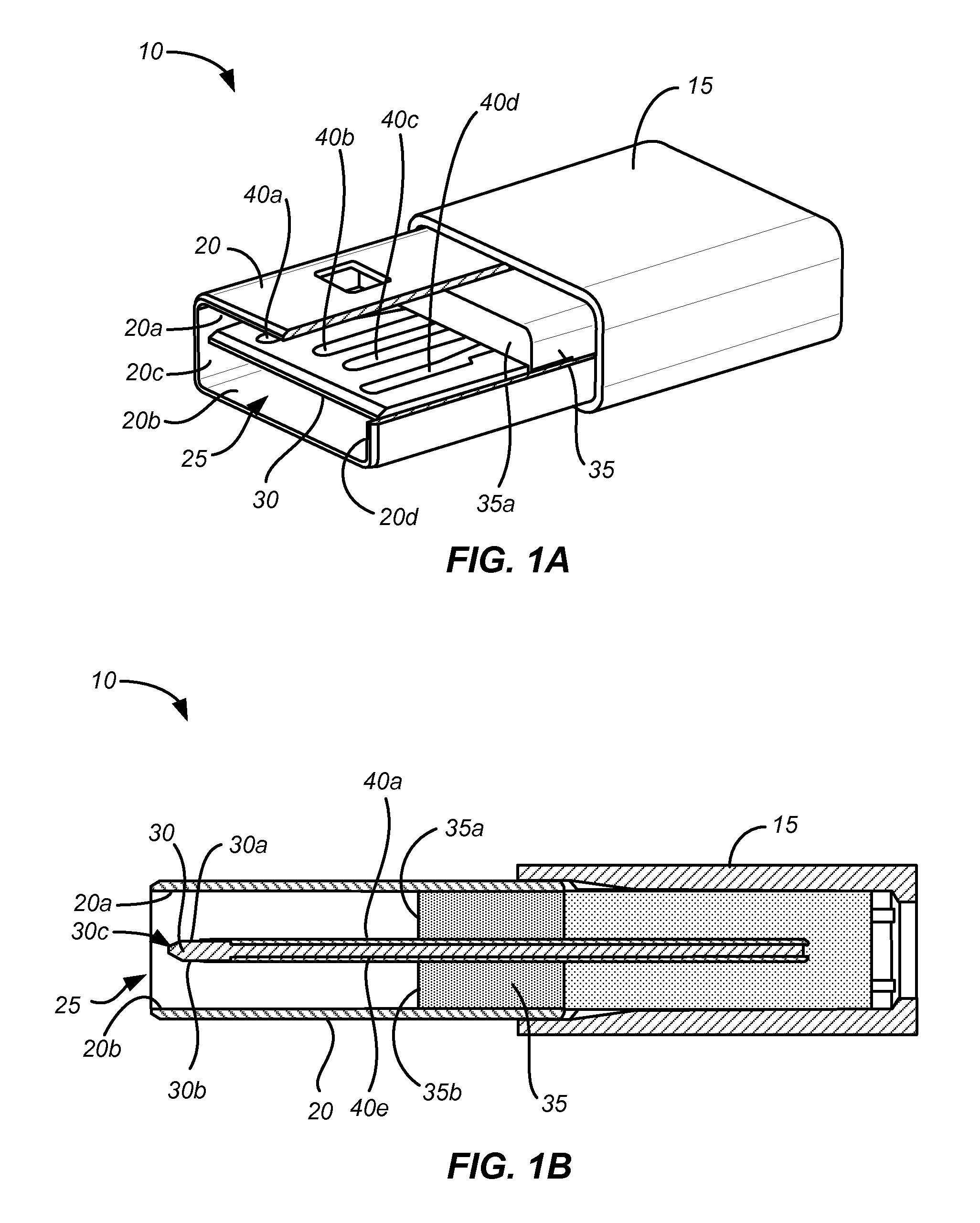
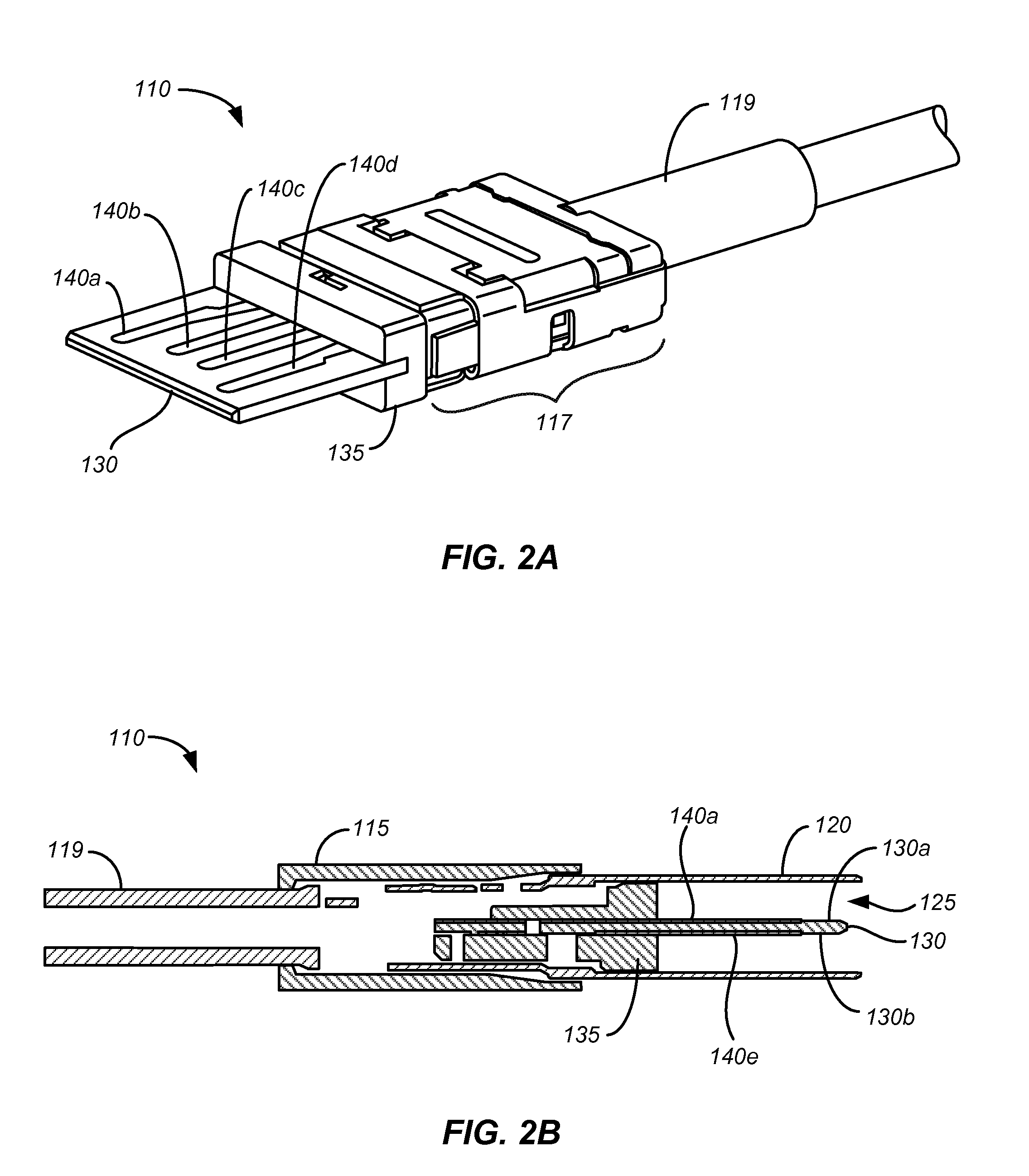
[0031]Embodiments can provide reversible or dual orientation USB plug connectors for mating with standard USB receptacle connectors, e.g., a standard Type A USB receptacle connector. Accordingly, the present invention may be compatible with any current or future electronic device that includes a standard USB receptacle connector. USB plug connectors according to the present invention can have a 180 degree symmetrical, du...


PUM


Abstract

Embodiments can provide reversible or dual orientation USB plug connectors for mating with standard USB receptacle connectors, e.g., a standard Type A USB receptacle connector. Accordingly, the present invention may be compatible with any current or future electronic device that includes a standard USB receptacle connector. USB plug connectors according to the present invention can have a 180 degree symmetrical, double orientation design, which enables the plug connector to be inserted into a corresponding receptacle connector in either of two intuitive orientations. Some embodiments of the present invention may be used with or require a non-standard USB receptacle connector. Thus, embodiments of the present invention may reduce the potential for USB connector damage and user frustration during the incorrect insertion of a USB plug connector into a corresponding USB receptacle connector of an electronic device.

Description

CROSS-REFERENCES TO RELATED APPLICATIONS[0001]This application claims benefit of U.S. Provisional Application No. 61 / 756,413, filed Jan. 24, 2013, and U.S. Provisional Application 61 / 765,602, filed Feb. 15, 2013, which are incorporated herein by reference for all purposes.BACKGROUND OF THE INVENTION[0002]The present invention relates generally to input / output electrical connectors such as data connectors.[0003]Many electronic devices include data connectors, such as Universal Serial Bus (USB) connectors, that receive and provide power and data. These electrical connectors are typically female receptacle connectors and are designed to receive a male plug connector. The plug connector may be on the end of a cable and plug into an electronic device, thereby forming one or more conductive paths for signals and power.[0004]USB connectors, like many other standard data connectors, require that male plug connectors be mated with corresponding female receptacle connectors in a single, speci...

Claims


Application Information

Patent Timeline
Patent Type & Authority Applications(United States)
IPC IPC(8): H01R12/81H01R13/64
CPCH01R12/81H01R13/64H01R29/00H01R24/60H01R13/055H01R24/28H01R2107/00
Inventor KAMEI, IBUKIJONES, WARREN Z.JOL, ERIC S.GOLKO, ALBERT J.SOOHOO, ERIC T.
Owner APPLE INC
Learn More