Touch force estimation in an FTIR-based projection-type touch-sensing apparatus

a touch-sensing apparatus and projection-type technology, applied in the field of estimation, can solve the problems of difficult to detect changes in size with sufficient accuracy, exhibit relatively small deformation with increased application force, and limited use of changes in touch area for force estimation, so as to reduce unwanted variability, increase the current speed of the touching object, and introduce unwanted latency

Inactive Publication Date: 2015-07-21
FLATFROG LAB
View PDF11 Cites 35 Cited by
  • Summary
  • Abstract
  • Description
  • Claims
  • Application Information

AI Technical Summary

Benefits of technology

[0014]A still further objective is to provide such an alternative technique with a reduced dependence on the size of the touch for estimating application force.
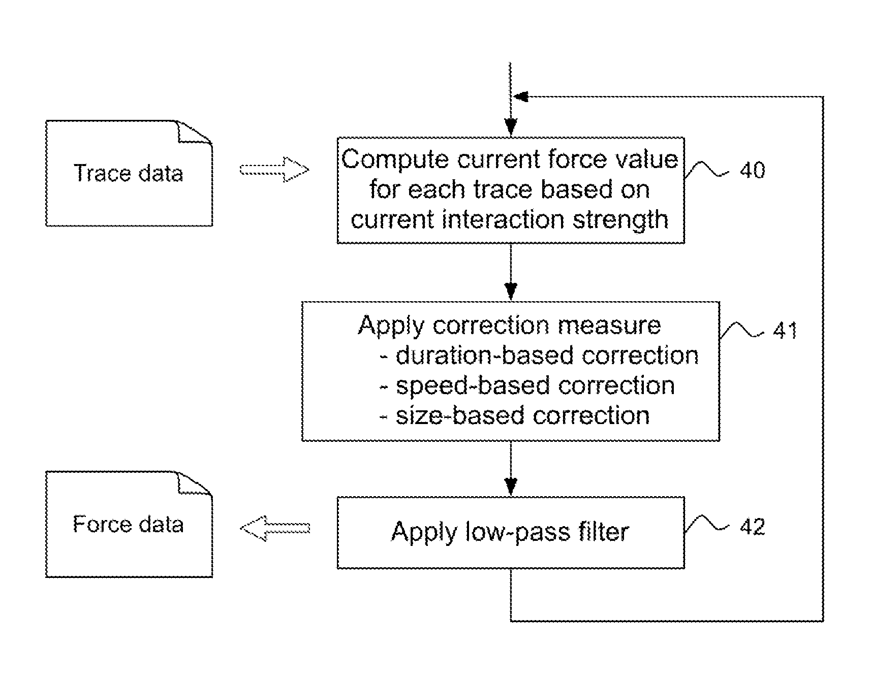
[0035]In one embodiment, the method further comprises the step of: selectively delaying an increase in cut-off frequency of the low-pass filter when the touching object is deemed to approach a stand-still on the touch surface. This may, e.g., operate to suppress the impact of unintentional variations in application force that may occur when the user halts the movement of the touching object.

Problems solved by technology

However, the use of changes in touch area for force estimation is limited to certain types of touching objects, since the objects need to be sufficiently soft and flexible to exhibit a variation in size with application force.
Many objects, such as fingertips, only exhibit a relatively small deformation with increased application force, and the change in size may be difficult to detect with sufficient accuracy.
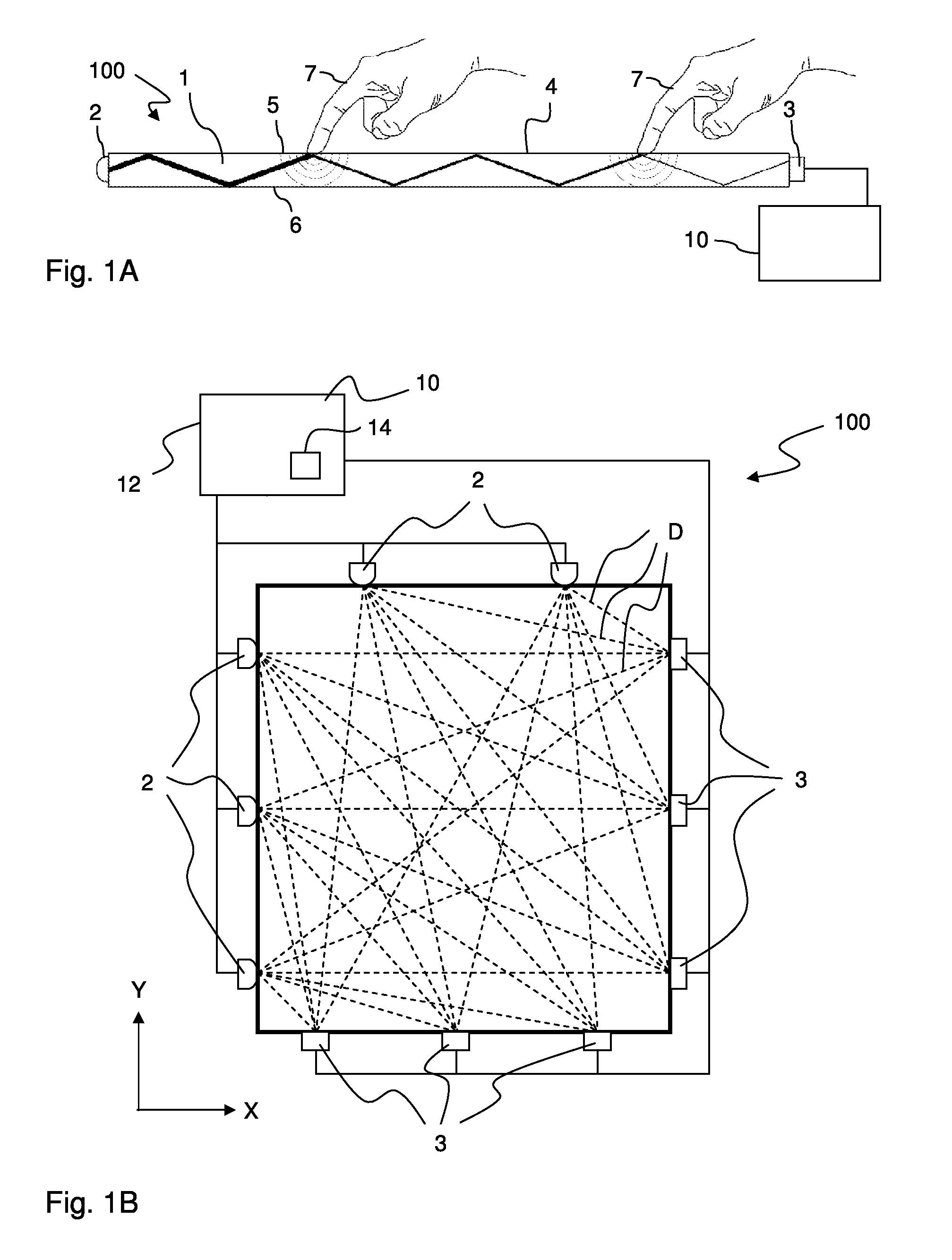
This increased contact may lead to a better optical coupling between the transmissive panel and the touching object, causing an enhanced attenuation (frustration) of the propagating radiation at the location of the touching object.
One such potential correction is based on the observation that a stationary object, i.e. a touching object that remains in essentially the same location on the touch surface over time, results in an asymptotic increase in attenuation over time even if the application force is unchanged.
However, this may lead to a step-change in the time series of force values when the touching object is accelerated past the low speed limit.
Such variability may be caused by measurement noise, image reconstruction noise and other processing noise, inaccuracies in one or more of the corrections (if applied), etc.
Furthermore, variations within the interaction pattern, and thus in the magnitude values, may occur when the moving object passes contamination on the touch surface, e.g. a fingerprint.
One drawback of using a low-pass filter is that it may introduce unwanted latency.

Method used


Image

  • Touch force estimation in an FTIR-based projection-type touch-sensing apparatus
  • Touch force estimation in an FTIR-based projection-type touch-sensing apparatus
  • Touch force estimation in an FTIR-based projection-type touch-sensing apparatus

Examples


Embodiment Construction

[0055]Before describing embodiments of the invention, a few definitions will be given.

[0056]A “touch object” or “touching object” is a physical object that touches, or is brought in sufficient proximity to, a touch surface so as to be detected by one or more sensors in the touch system. The physical object may be animate or inanimate.

[0057]An “interaction” occurs when the touch object affects a parameter measured by the sensor.

[0058]An “interaction strength” is a relative or absolute measure of the degree of interaction. The “interaction strength” may be represented as an “attenuation”.

[0059]An “interaction map” or “interaction pattern” is a two-dimensional (2D) distribution of interaction strength across the touch surface, or a portion thereof. If the interaction is presented as attenuation, the interaction map / pattern is also denoted an “attenuation map” or “attenuation pattern”.

[0060]A “touch” denotes a point of interaction as seen in the interaction pattern.

[0061]A “frame” or “i...


PUM


Abstract

A device implements a method for estimating the application force of a touching object onto a touch surface in an FTIR-based projection-type touch-sensing apparatus. The apparatus generates projection signals representing radiation that has propagated on a plurality of propagation paths by total internal reflection (TIR) inside a transmissive panel beneath a touch surface of the transmissive panel such that a touching object on the touch surface causes attenuation (frustration) of at least one of the projection signals. The device generates a time series of force values, which represent the application force, based on a time series of magnitude values, which represent a magnitude of a peak in two-dimensional interaction patterns generated by image reconstruction processing of the projection signals, the peak corresponding to the touching object on the touch surface. The force estimation may involve one or more corrections.

Description

CROSS-REFERENCE TO RELATED APPLICATIONS[0001]The present application claims the benefit of Swedish patent application No. 1251014-5, filed 11 Sep. 2012, and U.S. provisional application No. 61 / 699,503, filed 11 Sep. 2012, both of which are incorporated herein by reference.TECHNICAL FIELD[0002]The present invention generally relates to estimation of application force for touches on touch surfaces of optical touch-sensing systems, and in particular in relation to FTIR-based touch systems of projection-type.BACKGROUND ART[0003]Touch-sensing systems (“touch systems”) are in widespread use in a variety of applications. Typically, the touch systems are actuated by a touching object such as a finger or stylus, either in direct contact, or through proximity (i.e. without contact), with a touch surface. Touch systems are for example used as touch pads of laptop computers, in control panels, and as overlays to displays on e.g. hand held devices, such as mobile telephones. A touch panel that i...

Claims


Application Information

Patent Timeline
Patent Type & Authority Patents(United States)
IPC IPC(8): G06F3/042G06F3/041
CPCG06F3/0421G06F3/0414G06F2203/04109G06F3/0418
Inventor JOHANSSON, ANDREASOHLSSON, NICKLAS
Owner FLATFROG LAB
Why Eureka
Try Eureka