Optical coupling in touch-sensing systems using diffusively transmitting element

a technology of optical coupling and transmitting element, applied in the field of touch sensing system, can solve the problems of difficult and/or costly realization, increase the footprint of the touch system, and change in the light received by one or more detectors, etc., and achieve the effect of simple assembly and suited for mass production

Inactive Publication Date: 2015-07-23
FLATFROG LAB
View PDF25 Cites 42 Cited by
  • Summary
  • Abstract
  • Description
  • Claims
  • Application Information

AI Technical Summary

Benefits of technology

[0010]One objective is to provide an FTIR-based touch-sensitive apparatus which is robust and compact, while defining light propagation paths with well-defined extent.
[0012]Yet another objective is to enable an FTIR-based touch-sensitive apparatus that is simple to assemble and suited for mass production.
[0013]A still further objective is to provide an FTIR-based touch-sensitive apparatus with efficient use of light.

Problems solved by technology

An object that touches one of the boundary surfaces (“the touch surface”) will attenuate (“frustrate”) the light on one or more propagation paths and cause a change in the light received by one or more of the detectors.
This may be difficult and / or costly to achieve, especially if the panel is thin and / or manufactured of a comparatively brittle material such as glass.
Incoupling via the edge surface may also add to the footprint of the touch system.
Furthermore, it may be difficult to optically access the edge surface if the panel is attached to a mounting structure, such as a frame or bracket, and it is also likely that the mounting structure causes strain in the edge surface.
Such strain may affect the optical quality of the edge surface and result in reduced incoupling performance.
However, the prisms or wedges may add significant thickness and weight to the system.
The present applicant has found that the difference in thermal expansion between the plastic material and the glass may cause a bulky wedge to come loose from the panel as a result of temperature variations during operation of the touch system.
Even a small or local detachment of the wedge may cause a significant decrease in the performance of the system.

Method used


Image

  • Optical coupling in touch-sensing systems using diffusively transmitting element
  • Optical coupling in touch-sensing systems using diffusively transmitting element
  • Optical coupling in touch-sensing systems using diffusively transmitting element

Examples


Embodiment Construction

[0043]In the following, embodiments of the present invention will be presented for a specific example of a touch-sensitive apparatus. Throughout the description, the same reference numerals are used to identify corresponding elements.

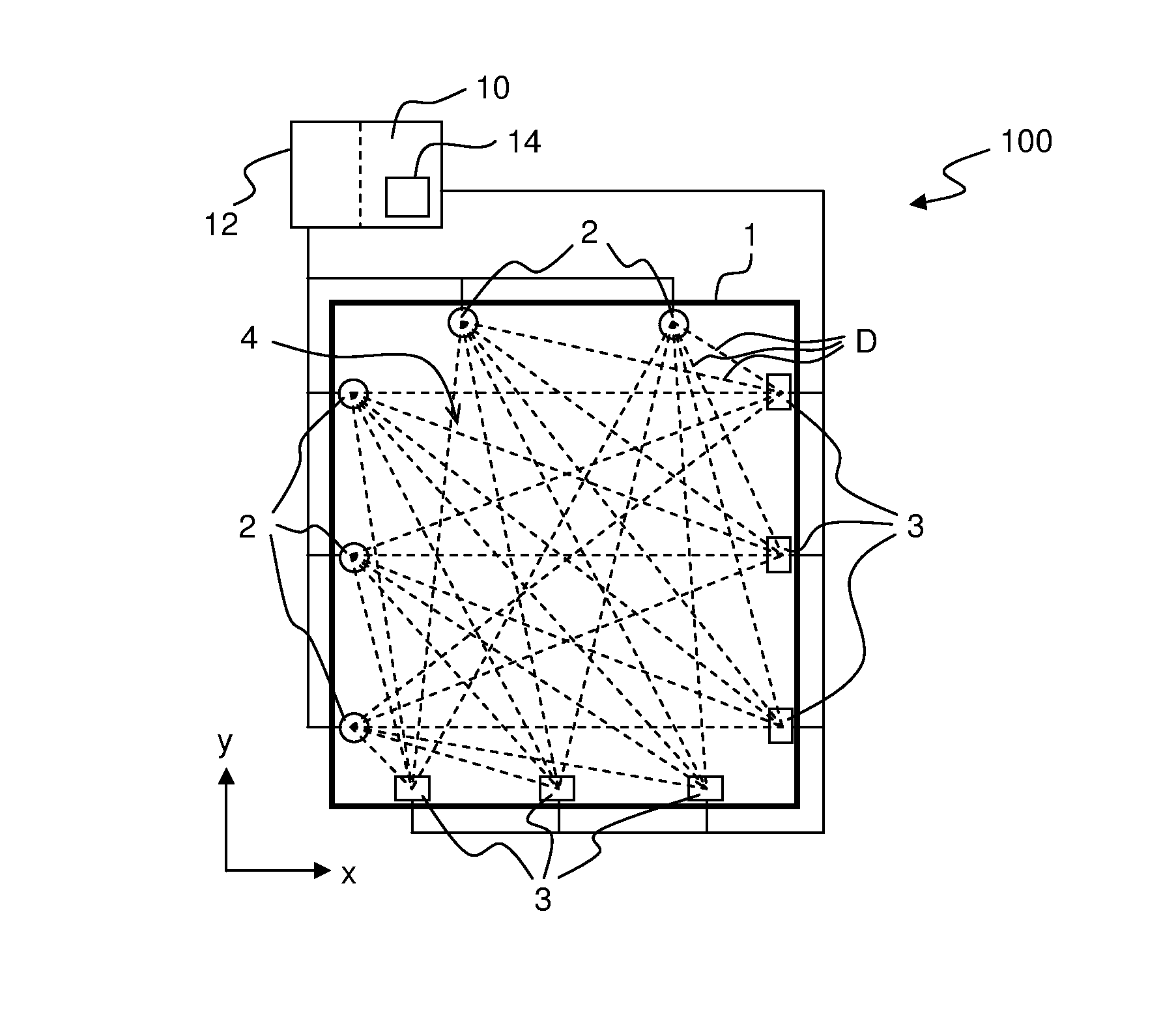
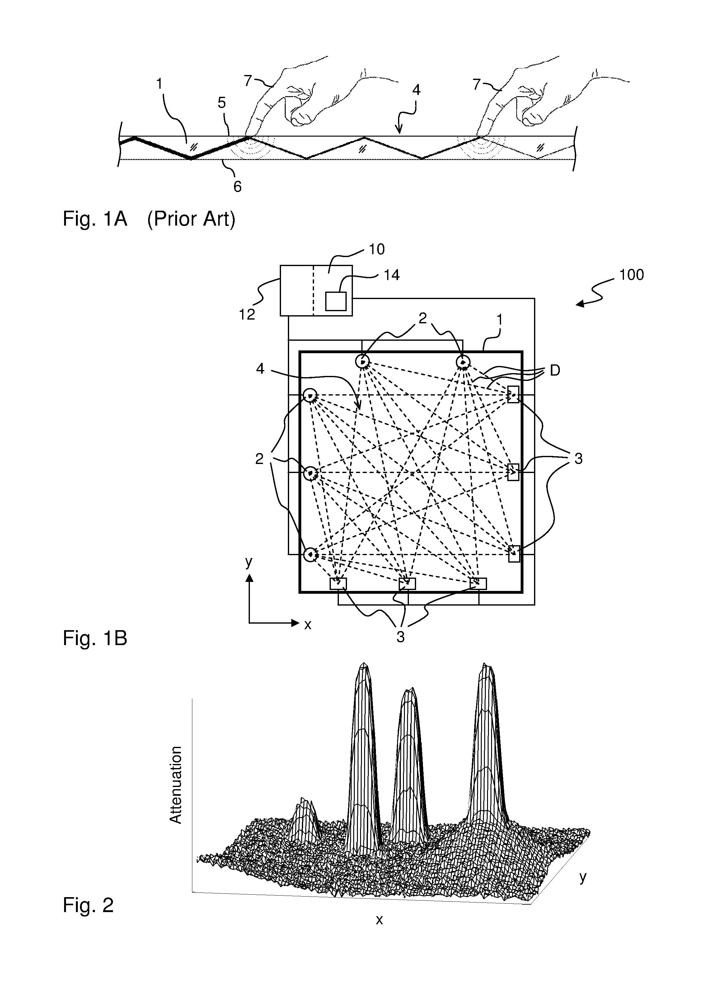
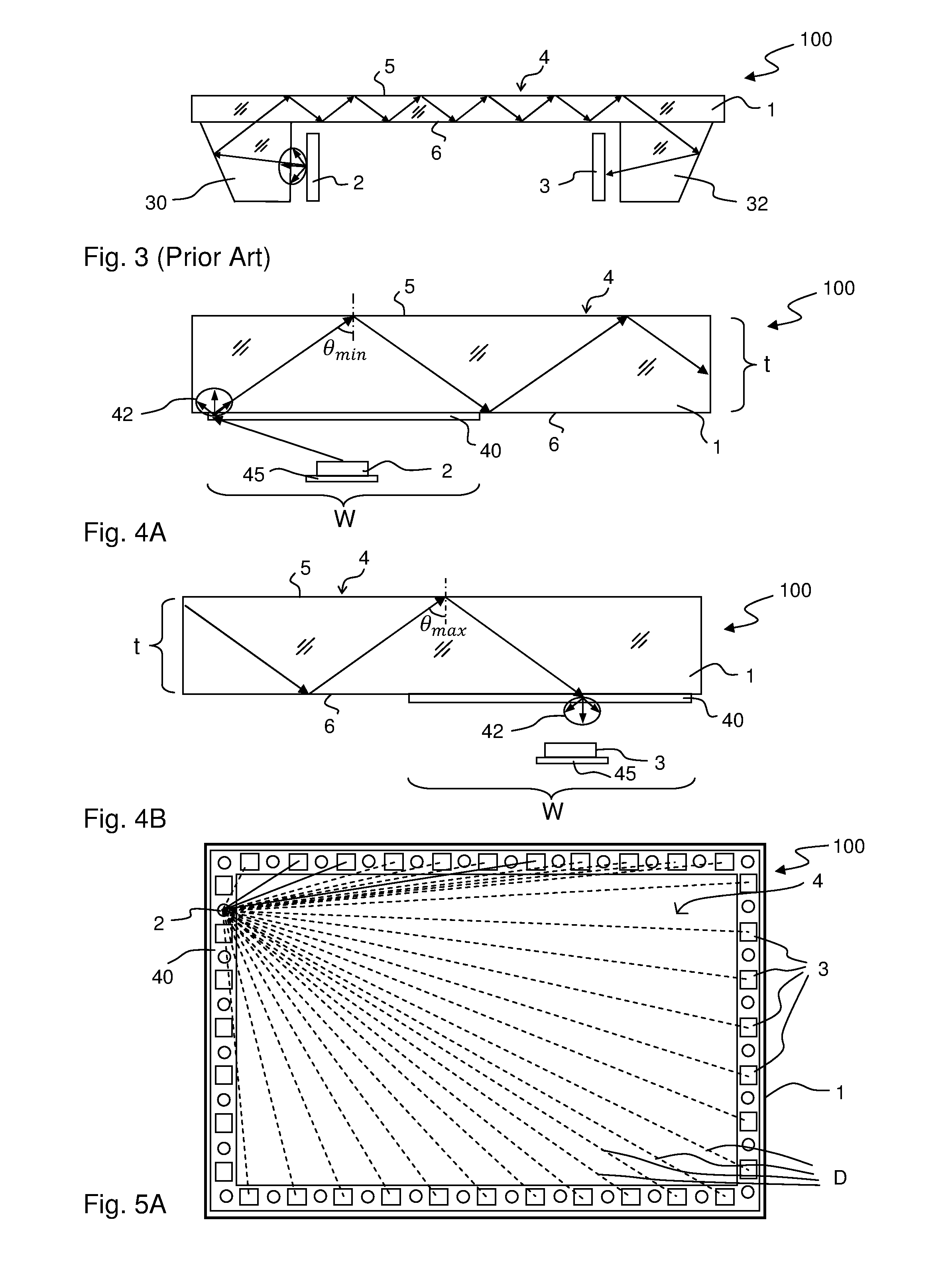
[0044]FIG. 1A illustrates the concept of touch detection based on attenuation by FTIR (Frustrated Total Internal Reflection) of propagating light. According to this concept, light is transmitted inside a panel 1 along a plurality of well-defined propagation paths. The panel 1 is made of solid material in one or more layers and may have any shape. The panel 1 defines an internal radiation propagation channel, in which light propagates by internal reflections. In the example of FIG. 1A, the propagation channel is defined between the boundary surfaces 5, 6 of the panel 1, and the front (top) surface 5 allows the propagating light to interact with touching objects 7 and thereby defines a touch-sensitive region 4 (“touch surface”). The interaction is enabled...


PUM


Abstract

A touch-sensitive apparatus operates by light frustration and comprises a light transmissive panel with a front surface and a rear surface. Light emitters and light detectors optically face the rear surface along a perimeter of a touch-sensitive region on the panel. At least one non-imaging, diffusively transmitting optical element is arranged on the rear surface along the perimeter of the touch-sensitive region. The light emitters are arranged to emit a respective beam of light onto the non-imaging optical element so as to generate, by diffuse transmission, propagating light that propagates by total internal reflection inside the panel across the touch-sensitive region, and the light detectors are arranged to receive detection light generated, by diffuse transmission, as the propagating light impinges on the non-imaging optical element, so as to define a grid of propagation paths across the touch-sensitive region between pairs of light emitters and light detectors.

Description

CROSS-REFERENCE TO RELATED APPLICATIONS[0001]The present application claims the benefit of Swedish patent application No. 1250890-9, filed 24 Jul. 2012, and U.S. provisional application No. 61 / 675,032, filed 24 Jul. 2012, both of which are incorporated herein by reference.TECHNICAL FIELD[0002]The present invention relates to touch-sensing systems that operate by propagating light by internal reflections along well-defined light paths inside a thin light transmissive panel, and in particular to optical solutions for defining the location of the light paths.BACKGROUND ART[0003]This type of touch-sensing system is known as an FTIR-based system (FTIR, Frustrated Total Internal Reflection). It may be implemented to operate by transmitting light inside a solid light transmissive panel, which defines two parallel boundary surfaces connected by a peripheral edge surface. Light generated by a plurality of emitters is coupled into the panel so as to propagate by total internal reflection (TIR...

Claims


Application Information

Patent Timeline
Patent Type & Authority Applications(United States)
IPC IPC(8): G06F3/042G06F1/16G02B6/43
CPCG06F3/0421G06F2203/04109G06F1/16G02B6/43
Inventor BERGSTROM, HAKANWASSVIK, OLACRAVEN-BARTLE, THOMAS
Owner FLATFROG LAB
Why Eureka
Try Eureka