
Frame assembly for display panel

a display panel and frame technology, applied in the direction of identification means, display means, instruments, etc., can solve the problems of easy damage to the display panel or the frame provided with the display panel, the need to re-manufacture and the need to replace printed sheets or signboards

Active Publication Date: 2014-07-31
JSLCD
View PDF5 Cites 32 Cited by
  • Summary
  • Abstract
  • Description
  • Claims
  • Application Information

AI Technical Summary

Benefits of technology

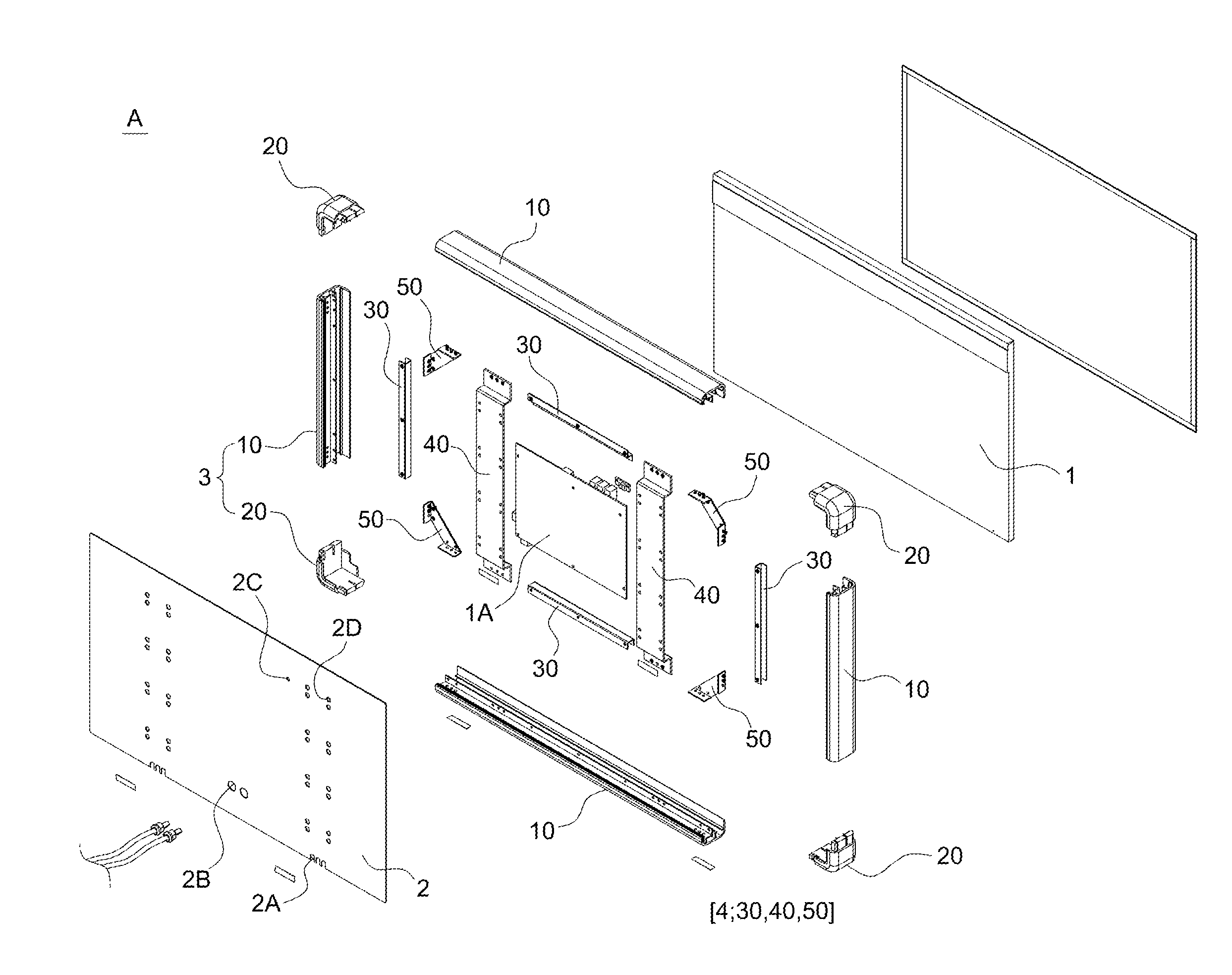
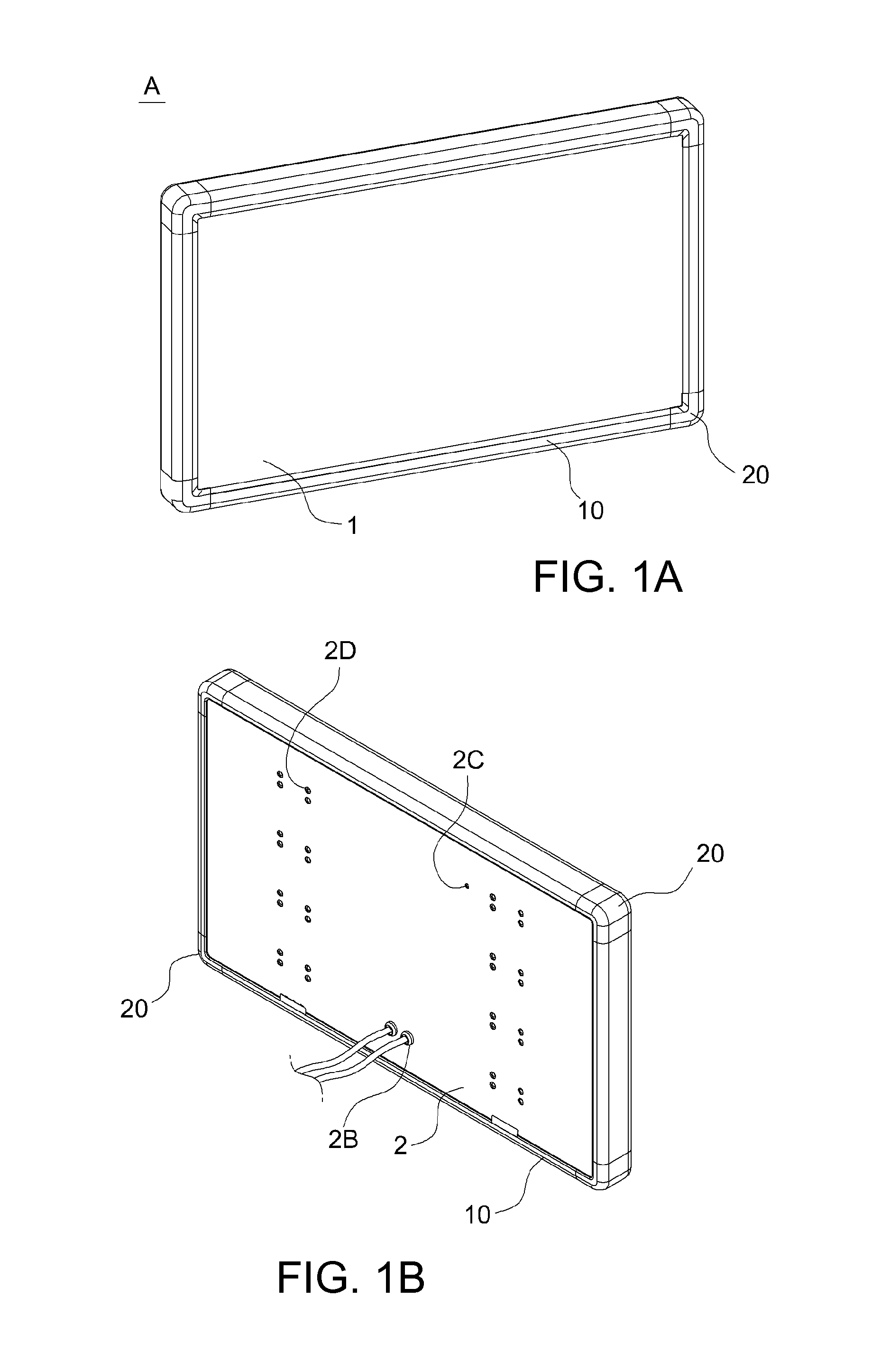
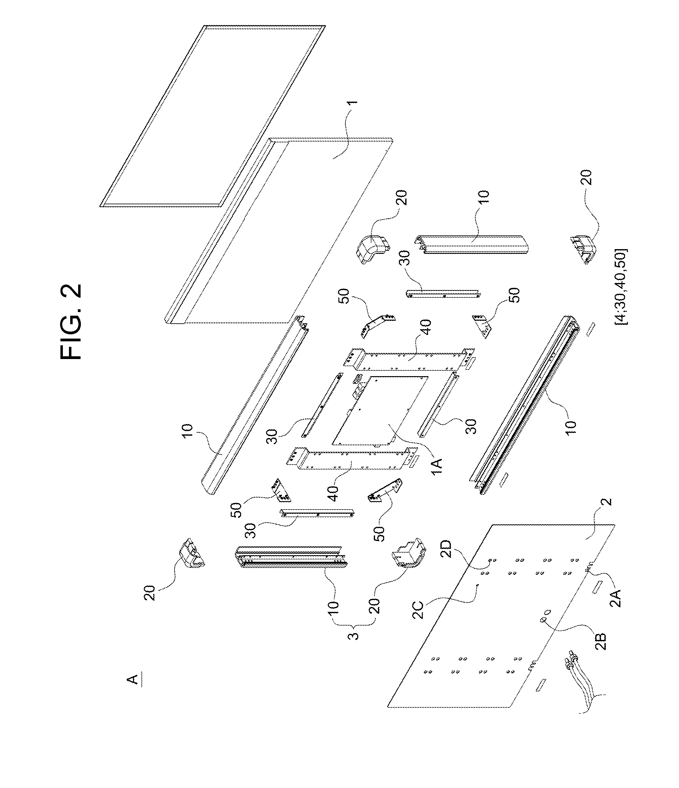
The present invention provides a frame assembly for a display panel that includes an assembling means to secure reliable coupling among elements of the frame assembly. This prevents damage to the housing in which the display panel is installed and reduces the assembly work time. The frame assembly includes a frame and a connection member that have simple structures to ensure reliable coupling among the elements. The elements can be systematically coupled to each other using a single fastening member. The frame assembly also has a tool insert hole and a tool insert notch to enable easy assembly process and a closed structure.

Problems solved by technology

However, the above-mentioned conventional techniques are disadvantageous in that when a change in information (a company name or advertisement contents) to be delivered is required, a printed sheet or signboard must be re-manufactured.
However, in the same manner as billboards installed in buildings, buses, etc., the LED board (display panel) is exposed to the outside, so that people easily come into contact with the LED board.
Particularly, in the case of a billboard installed in a bus, there is a problem in that the display panel or the frame provided with the display panel may be easily damaged by impact caused by vibration when the bus is being operated.

Method used


Image

  • Frame assembly for display panel
  • Frame assembly for display panel
  • Frame assembly for display panel

Examples


Embodiment Construction

[0030]Hereinafter, the present invention will be described in detail with reference to the attached drawings.

[0031]This invention may, however, be embodied in many different forms, and should not be construed as limited to the embodiments set forth herein. Rather, all changes that fall within the bounds of the present invention, or the equivalence of the bounds are therefore intended to be embraced by the present invention.

[0032]The same reference numerals throughout the drawings, that is, the same reference numerals for the second digit or the first digit, or for the second digit, the first digit and a letter of the alphabet, denote elements having the same function. If not specifically mentioned otherwise, the elements denoted by the reference numerals are to be assumed to comply with the above-mentioned reference scheme.

[0033]In the drawings, the thicknesses of lines or the sizes of elements may be exaggerated or simplified to more clearly and conveniently illustrate the present ...


PUM


Abstract

Disclosed herein is a frame assembly for a display panel. The frame assembly includes a display panel, a rear cover, a housing and an assembling means. The housing includes a plurality of frames which enclose the display panel and the rear cover. Each frame has a sidewall, and a connection member which connects the frames to each other. The assembling means is installed in the housing to provide a closed structure and is provided to ensure coupling force among the display panel, the rear cover and the housing. The assembling means includes a fastening bracket which presses the display panel onto the frames of the housing and fastens the display panel to the frames, a support bracket which supports the rear cover, and an auxiliary bracket which assists connection between the adjacent frames.

Description

BACKGROUND OF THE INVENTION[0001]1. Field of the Invention[0002]The present invention relates generally to frame assemblies for display panels and, more particularly, to a frame assembly for installation of a display panel which is used for an electronic panel, a billboard, a monitor, etc. that is installed in a building, a vehicle or the like, the frame assembly having an assembling means for making the coupling force between the frames reliable, thus preventing the frame assembly from being damaged by external impact caused, for example, by vibration.[0003]2. Description of the Related Art[0004]Generally, conventional signboards, billboards, etc. include a housing which is provided with a transparent cover that is printed with advertisement contents, and a light source, such as a fluorescent lamp, an LCD, etc., which is installed in the housing.[0005]A representative example of techniques that pertain to conventional signboards, billboards, etc. was proposed in Korean Patent Laid-...

Claims


Application Information

Patent Timeline
Patent Type & Authority Applications(United States)
IPC IPC(8): G09F15/00
CPCG09F15/00G09F9/30G09F13/18G09F15/0012G09F2013/1881G09F9/00
Inventor MOON, JONG SUB
Owner JSLCD
Learn More