Catheter device having a coupling device for a drive device

a technology of driving device and coupling device, which is applied in the field of mechanical engineering and precision engineering, can solve the problems of high mechanical and thermal stress, significant over-dimensioning, and high cost of magnetic coupling of this type, and achieves reliable and easy-to-produce connection, increase the safety of the patient and the functional capacity of the shaft, and facilitate the effect of disassembly

Active Publication Date: 2019-01-08
ECP ENTWICKLUNGSGMBH
View PDF258 Cites 7 Cited by
  • Summary
  • Abstract
  • Description
  • Claims
  • Application Information

AI Technical Summary

Benefits of technology

[0028]For a reliable and easily producible connection between the hollow catheter and the coupling device, on the one hand, and the drive device, on the other hand, a locking connection device can advantageously be provided so that the corresponding connection can also be easily detached. This is particularly advantageous if one of the elements, normally the drive device, is intended to be used multiple times and the parts are separated after use on one patient. The catheter-side elements are normally delivered in sterile packaging, used on the patient after unpacking and connected to an individually sterilised drive device.
[0029]In order to increase the safety of the patient and the functional capacity of the shaft further, it can be provided advantageously in addition that, in addition to the mentioned germ barrier, an additional germ barrier is provided on the distal side of the shaft seal and of the coupling cavity, said germ barrier being able to be configured for example in the shape of a shaft rinsing device. In order to assist their flexibility

Problems solved by technology

In particular at the high speeds of rotation often required, intensive deformation of the shaft takes place which causes high mechanical and thermal stress.
Magnetic couplings of this type are however substantially more expensive and sensitive relative to conventional couplings.
In order to transmit the required tor

Method used


Image

  • Catheter device having a coupling device for a drive device
  • Catheter device having a coupling device for a drive device
  • Catheter device having a coupling device for a drive device

Examples


Embodiment Construction

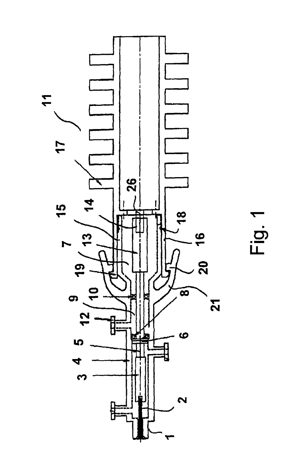
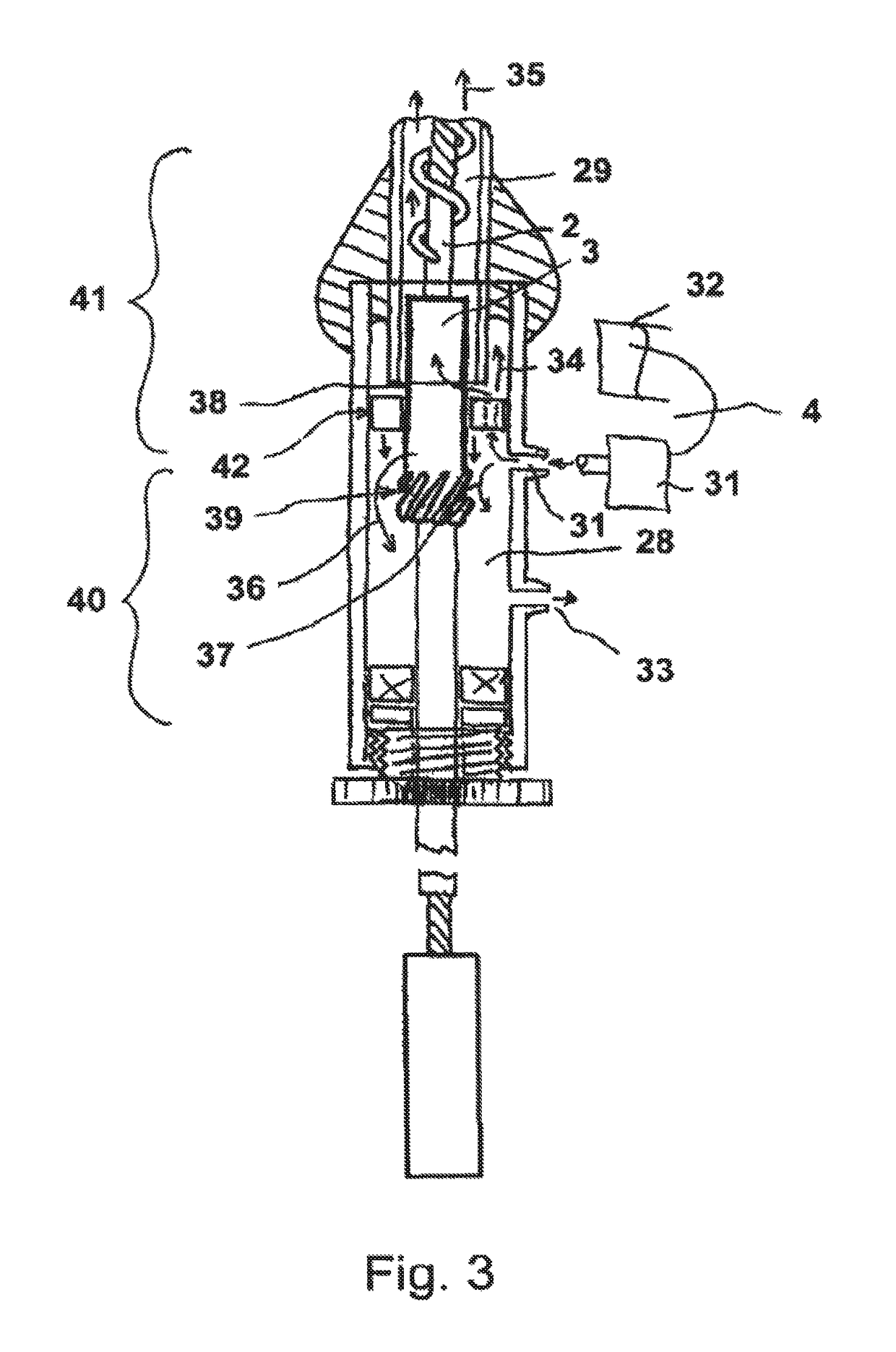
[0035]On the left side, FIG. 1 shows the hollow catheter 1 with the flexible shaft 2 which is guided in the catheter cavity and is connected in a non-rotatable manner to a first connection part 3. The first connection part 3 is situated in the region of a shaft rinsing device 4 which is dealt with in more detail further on in connection with FIG. 3. On the other side of the first connection part 3, an extension 5 of the shaft 2 is connected and is guided through a shaft seal 6 in a sealed manner from the shaft rinsing device 4 to a coupling cavity 7.

[0036]On the other side of the shaft seal 6, a first bearing 8 is connected, which guides the shaft extension 5 and delimits a partial chamber 9 which can be filled or is filled with gel on the catheter side. A second bearing 10 delimits the partial chamber 9 towards the drive device 11.

[0037]A filling opening 12 through which the partial chamber 9 can be filled with a germicidal gel or a viscous germicidal liquid is provided. The shaft ...


PUM


Abstract

The invention relates to a catheter device, having a hollow catheter in the catheter cavity of which a moveable shaft is guided, having a proximal coupling device, for detachable coupling of a drive device, the coupling device having a coupling cavity which is open towards the drive device and into which the shaft or an extension of the shaft protrudes with a connection element for mechanical coupling of a motor shaft, the coupling cavity having a germ barrier for reducing the pathogenicity of pathogenic substances or microorganisms.

Description

BACKGROUND OF THE INVENTION[0001]The invention resides in the field of mechanics or mechanical engineering and precision engineering and can be used in particular in the construction of small instruments for invasive use in medical technology.[0002]Instruments which can be actuated from outwith the body via flexible shafts are often used in particular in minimally invasive medicine. These shafts are normally guided through catheters which are introduced into the body through small openings or naturally occurring body vessels under particularly sensitive surrounding conditions.[0003]A particular application form resides for example in the actuation of liquid pumps in microconstructional form which are used for example as heart pumps and which can be introduced into a ventricle with a heart catheter.[0004]Particular requirements thereby reside not only in the small constructional size of the corresponding pumps, as also when using other microinvasive instruments actuated via such a sh...

Claims


Application Information

Patent Timeline
IPC IPC(8): A61M25/00A61M1/10A61B17/3207A61M1/12A61M25/01A61B17/00A61M60/13A61M60/216A61M60/414A61M60/818A61M60/829
CPCA61M1/1034A61B17/320758A61B2017/00889A61M1/101A61M25/0105A61M1/1036A61M1/122A61M1/125A61M1/1013A61M60/414A61M60/419A61M60/148A61M60/829A61M60/216A61M60/13
Inventor SIMON, CORNELIAHONSELMANN, JULIABAUMGAERTEL, JENSLIEBING, REINER
Owner ECP ENTWICKLUNGSGMBH
Why Eureka
Try Eureka