Hip prosthesis

a hip joint and prosthesis technology, applied in the field of hip prosthesis, can solve the problems of weakening the bond between the bone and the prosthesis, and the stem displacement is greater than the natural displacement of the stem, so as to improve the stability of the hip joint endoprosthesis

Inactive Publication Date: 2005-11-24
ZELENER LEV +3
View PDF27 Cites 10 Cited by
  • Summary
  • Abstract
  • Description
  • Claims
  • Application Information

AI Technical Summary

Benefits of technology

[0008] Thus, a primary object of the present invention

Problems solved by technology

Furthermore, localized pressure generated by the prosthesis parts causes greater than naturally occurring displacement of the stem from its initial position.
The clinical practice and numerous data show that this approach may not fully take into consideration the following: even after milling of the c

Method used


Image

  • Hip prosthesis
  • Hip prosthesis
  • Hip prosthesis

Examples


Embodiment Construction

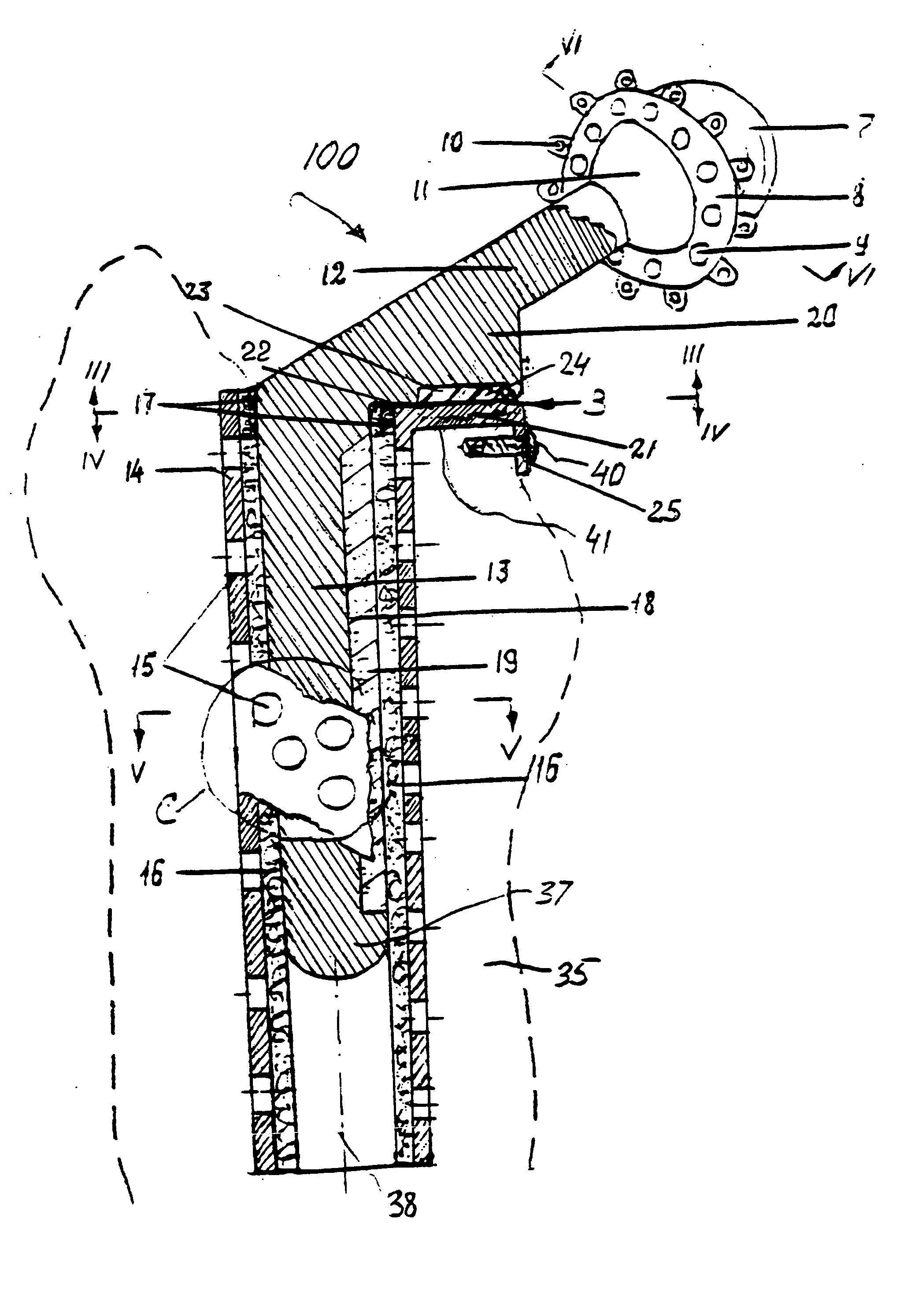
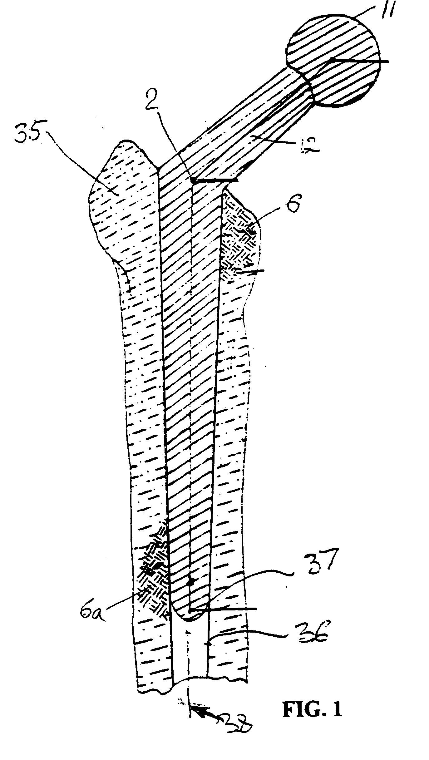
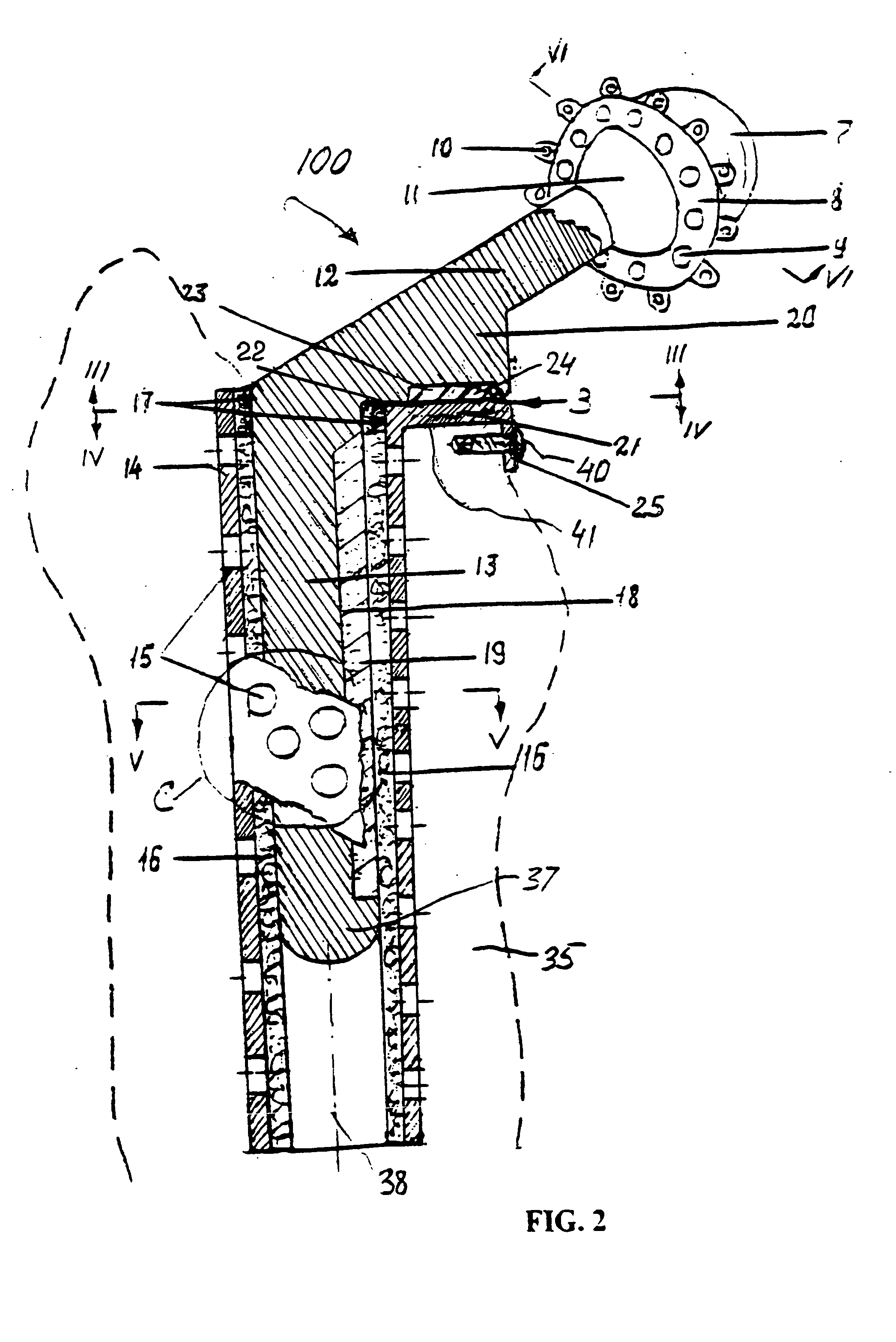
[0026] Referring to FIGS. 1-2, the anatomical structure of the hip joint includes the femur diaphysis, further referred to as a bone 35, neck and head 11. If a situation requires the hip replacement, it is performed by removing the neck, forming a channel 36 within the bone 35 and introducing a stem 13 (FIG. 2) of a prosthesis 100 into the channel 36. Formed integrally with the stem 13 is a neck portion 12 of the prosthesis 100, which extends angularly from the stem 13 into a cup 7 that is attached to the head of the bone.

[0027] As follows from the clinical practice, loading of the prosthesis cup leads to the greatest bone resorption of the femur diaphysis in its upper medial part 34, as this is where the most of the body weight load is applied. The prosthesis stem 13 and particularly its distal end 37, are pushed laterally away form the median plan 39 (FIG. 4), as shown by an arrow “38” in FIG. 1 due to the inherent motion of the bone 35 occurring as a result of applied loads.

[00...


PUM


Abstract

An endoprosthesis utilizes a biomechanical structure based on the new inventive lever model of first degree. Contrary to the widespread practice, the inventive structure has a stem placed inside the femur bone, which is not rigidly attached to this bone. Accordingly, the bone, following its known tendency to slightly pivot away from the medial plane of the body in response to the loads, does not directly contact the stem. The neck portion experiences even greater loads then the stem. The supporting anchor has a region extending laterally from the stem and pressing against a supporting surface of the housing, which also extends laterally from the body of the housing. Since the stem, supporting anchor and neck are typically constitute a one-piece component, the lateral surfaces of the supporting anchor and housing are in continuous frictional contact during displacement of the stem and housing relative to one another.

Description

BACKGROUND OF THE INVENTION [0001] Replacement devices such as artificial joints in general and especially those for the hip have been known for many years. Such replacement devices include substitute members for the two parts of the natural joint, namely the femoral head, which is joined to the femur, and the hip socket, which receives and cooperates with the head to provide a natural universal joint. [0002] Replacement of the natural hip joint parts is necessary when deterioration has occurred to one or both of the natural femoral head and socket. Ideally, the replacement members should reproduce the structure and function of the original members. For example, it is important that the femoral head be securely attached to the femur, that the head be received within the socket and that the resulting joint be produced with the desirable degree of resilience or cushioning. [0003] All known prior art, for example U.S. Pat. No. 4,770,661 and U.S. Pat. No. 4,159,544 disclose a system ass...

Claims


Application Information

Patent Timeline
IPC IPC(8): A61B17/86A61F2/00A61F2/28A61F2/30A61F2/32A61F2/34A61F2/36
CPCA61B17/86A61F2310/00293A61F2/30767A61F2/32A61F2/34A61F2/36A61F2/3662A61F2002/2835A61F2002/30024A61F2002/30217A61F2002/30289A61F2002/30365A61F2002/30448A61F2002/30574A61F2002/30578A61F2002/30677A61F2002/30708A61F2002/30733A61F2002/30738A61F2002/30777A61F2002/30787A61F2002/30805A61F2002/3082A61F2002/30919A61F2002/3432A61F2002/3611A61F2002/3625A61F2220/0033A61F2220/005A61F2230/0067A61F2230/0091A61F2250/0021A61F2250/0084A61F2310/00017A61F2310/00023A61F2310/00131A61F2/30734
Inventor ZELENER, LEVSHEREPO, KONSTANTINZELENER, MARINASVETLANOV, ANTON
Owner ZELENER LEV
Why Eureka
Try Eureka