Eureka AIR delivers breakthrough ideas for toughest innovation challenges, trusted by R&D personnel around the world.

Device for coupling an actuator for controlling the landing gear of an aircraft

Active Publication Date: 2014-07-31
MESSIER BUGATTI DOWTY SA
View PDF1 Cites 3 Cited by
  • Summary
  • Abstract
  • Description
  • Claims
  • Application Information

AI Technical Summary

Benefits of technology

[0012]Thus, when the actuator is activated, e.g. in order to raise the undercarriage towards its stowage position, the actuator force acts against the pre-loading means, if necessary, in order to bring the lever towards its working position, such that the actuator is positively positioned relative to the structure of the aircraft. In contrast, when the actuator is not activated, e.g. when the undercarriage is locked in its deployed position, the lever acts like a fil

Problems solved by technology

In general, since the actuator is mounted in parallel with the side-brace, it is liable to transmit forces that it must withstand, and it is thus liable to stress its couplings.
However, that does n

Method used


Image

  • Device for coupling an actuator for controlling the landing gear of an aircraft
  • Device for coupling an actuator for controlling the landing gear of an aircraft
  • Device for coupling an actuator for controlling the landing gear of an aircraft

Examples


Example

DETAILED DESCRIPTION OF THE FIGURES

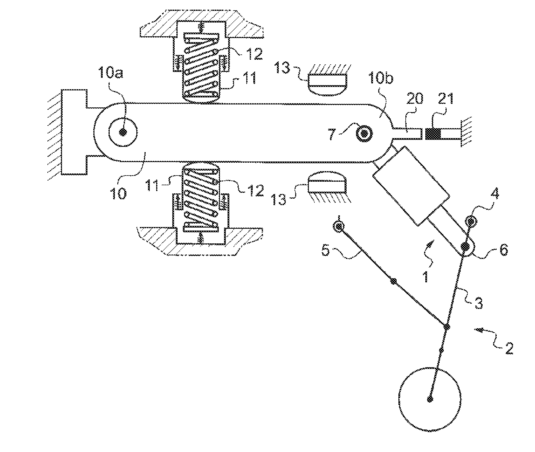
[0018]With reference to FIG. 1, the coupling device of the invention serves to couple a telescopic actuator 1 to an aircraft structure, the actuator 1 serving to operate an undercarriage 2 for which there can be seen the strut-leg 3 hinged at 4 to the structure of the aircraft, and the side-brace 5 (shown in this figure in the aligned and locked position to hold the undercarriage in the deployed position).

[0019]The actuator 1 is hinged at one of its ends 6 to the strut-leg 5 of the undercarriage, and at its other end 7 to the structure of the aircraft via a coupling device of the invention.

[0020]This coupling device comprises:

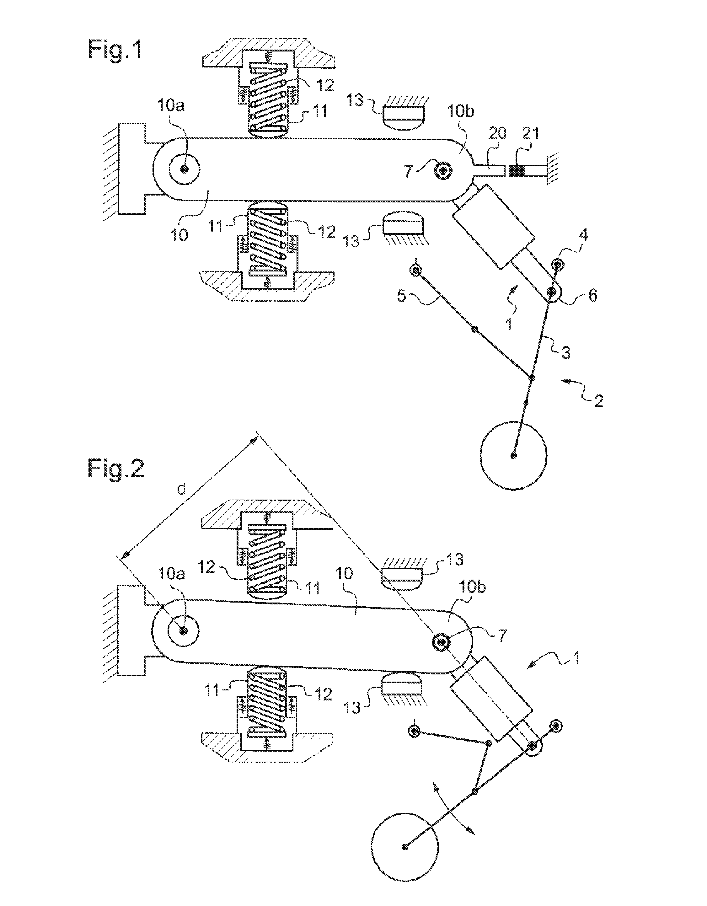
[0021]a lever 10 having one end 10a hinged to the structure of the aircraft, and one end 10b to which the end 7 of the actuator 1 is hinged;

[0022]pre-loading means comprising, in this example, two pushers 11 arranged on either side of the lever 10 to act on each side of the lever 10 and pre-loaded by springs 12 pushing the pus...


PUM


Abstract

A device for coupling an actuator for operating an aircraft undercarriage to an aircraft structure. The device comprises a lever having a first end for hinging to the structure of the aircraft, and a second end to which the actuator is hinged, a pre-loading structure acting on the lever to urge it towards a stable rest position that is occupied by the lever in the absence of any force transiting through the actuator; and an abutment structure defining at least one working position for the lever when the actuator is activated.

Description

[0001]The invention relates to a device for coupling an actuator for operating an aircraft undercarriage.TECHNOLOGICAL BACKGROUND OF THE INVENTION[0002]Undercarriages are generally hinge-mounted to the structure of an aircraft, e.g. via two ball joints in alignment mounted on the aircraft in order to receive pivots that are secured to the undercarriage. A stabilizer member referred to as a “side-brace” serves, when the undercarriage is deployed, to hold it in the deployed position. The side-brace is then locked in position and triangulates the undercarriage to prevent it from pivoting about the axis defined by the pivots.[0003]An operating actuator, generally a telescopic actuator, is coupled between the structure of the aircraft and the undercarriage in order to operate it. In general, the operating actuator is used actively to cause the undercarriage to rise towards its stowage position, and it is used to slow the downward movement of the undercarriage towards its deployed positio...

Claims


Application Information

Patent Timeline
IPC IPC(8): B64C25/20
CPCB64C25/20B64C25/26B64C25/62B64C25/58
Inventor BLANPAIN, THIERRYDUCOS, DOMINIQUECAMPBELL, EDOUARD
Owner MESSIER BUGATTI DOWTY SA
Why Eureka
Eureka Blog
Learn More