Electronic simulation candle

Active Publication Date: 2014-08-07
FOSHAN MOGEN INTELLIGENT TECH CO LTD
View PDF2 Cites 92 Cited by
  • Summary
  • Abstract
  • Description
  • Claims
  • Application Information

AI Technical Summary

Benefits of technology

[0026]1. the flame piece swinger disclosed by the present invention, by the support of the top of the support rod against the top of the inner space accommodating the hollow tapered swinger, is allowed to wobble or swing irregularly, thus to drive the flame piece body above the flame piece swinger to wobble or swing irregularly in multiple directions, so as to create a more realistic effect of flame flickering;
[0027]2. as the flame piece of an existing electronic simulation candle is movably supported or hung onto an enclosure via a wire or support rod, the wire or support rod may be seen at a close look of the flame piece, as a result, the electronic candle is not so realistic with low degree of simulation; instead, the flame pi

Problems solved by technology

The degree of simulation is limited.
However, the disclosed flame piece is pivoted at an upper opening of the mechanism via a wire, so the visual aesthetics will be destroyed by the wire when viewers get close to appreciate the simulation candles.
However, the di

Method used


Image

  • Electronic simulation candle
  • Electronic simulation candle
  • Electronic simulation candle

Examples


first embodiment

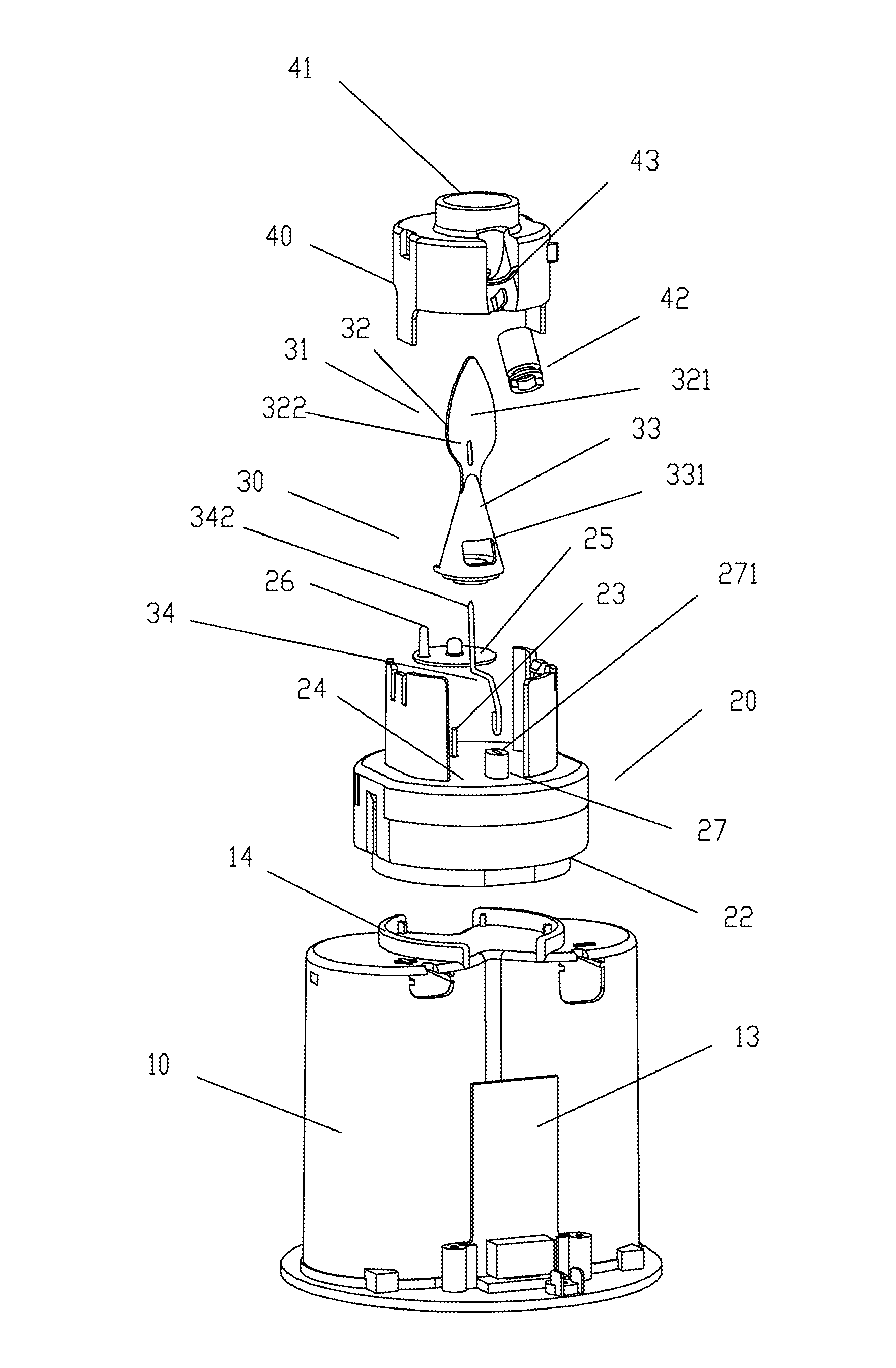
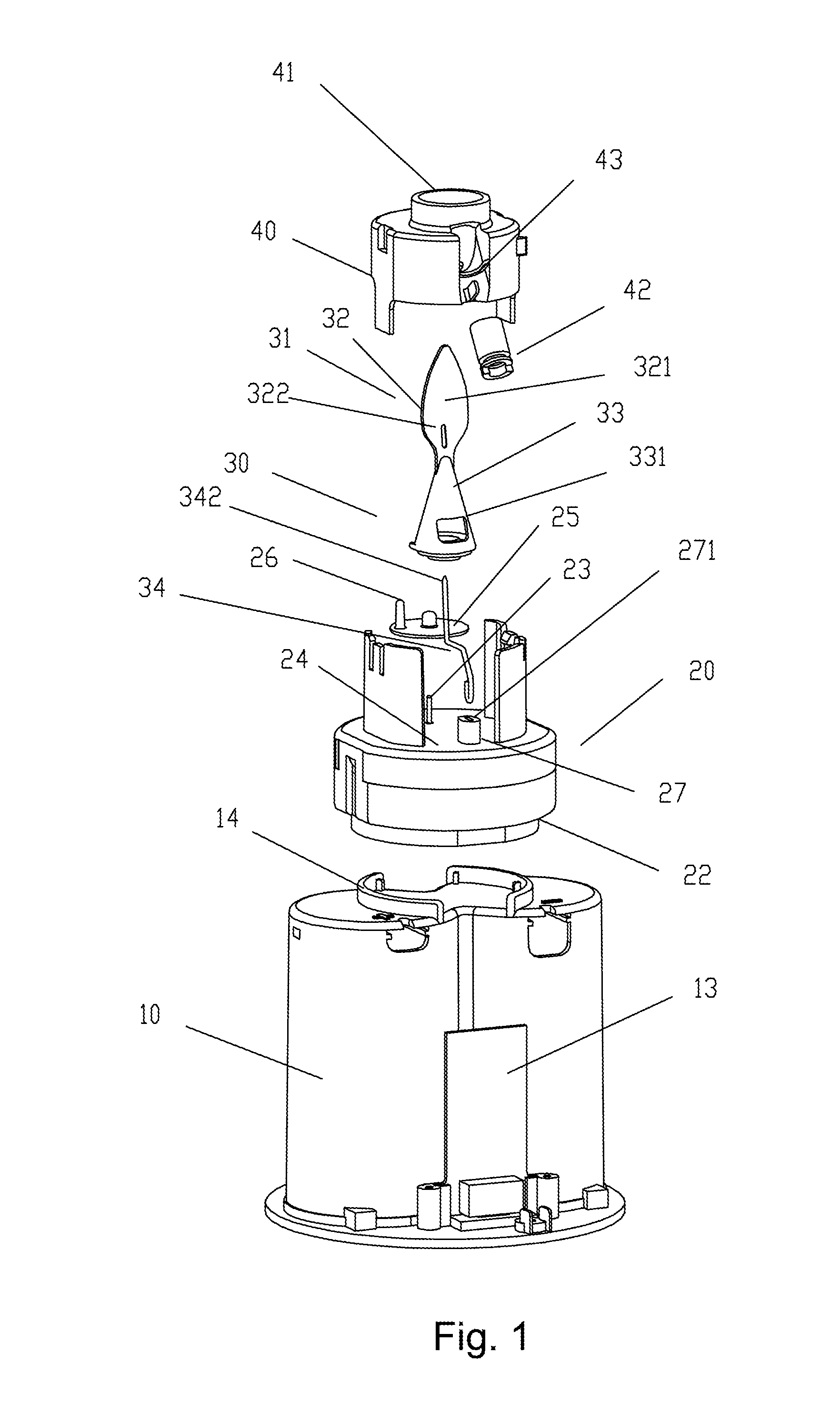
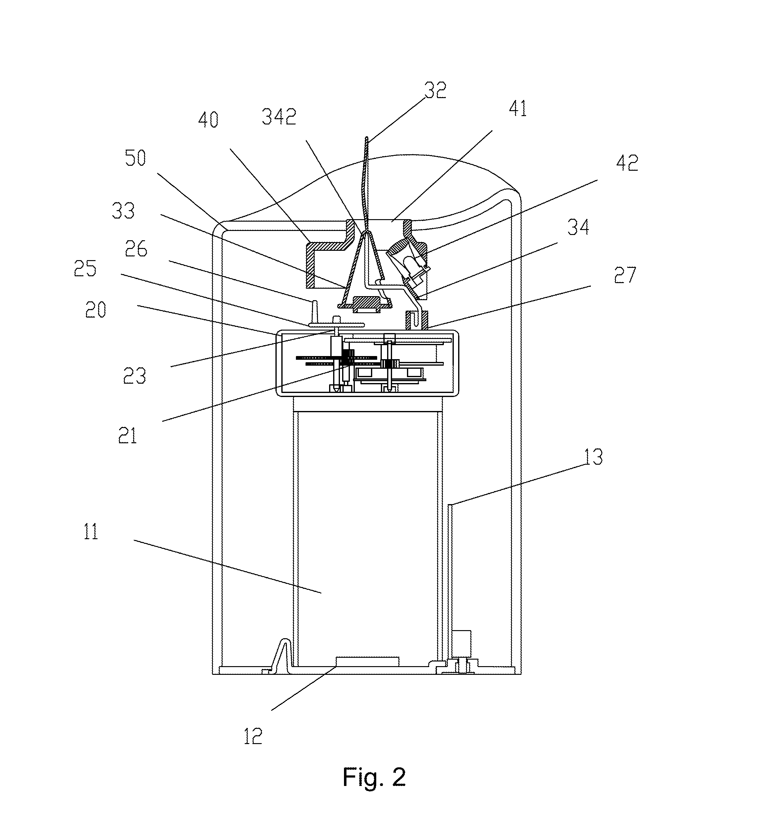
[0038]FIG. 1 to FIG. 3 show the present invention. The disclosed electronic simulation candle mainly comprises a power supply base 10, a power driven device 20, a flame piece swinger 30 and a light source fixation base 40. The power driven device 20 is electrically connected to the power supply base 10 and disposed above the power supply base 10. The light source fixation base 40 is disposed above the power driven device 20. The flame piece swinger 30 is disposed between the power driven device 20 and the light source fixation base 40. The power supply base 10 is an upright base having an accommodation space 11 therein, which accommodation space 11 can be used for accommodating batteries (not shown) and then closed via a cover plate 12 on the bottom thereof. A circuit board 13 electrically connected to the power supply base 10 is provided outside the power supply base 10. A fixed base 14 is disposed in the top center of the power supply 10.

[0039]The power driven device 20 consists o...

third embodiment

[0047]In addition, FIG. 6 shows the present invention. A modification is that the fixed column 27′ for inserting the support rod 34 is provided on the outer side of the upper surface of the turntable 25′. In addition, left and right limiting stand columns 29 and 29′ are provided on the chassis 22′ outside the turntable 25′. A positioning driving lever 251′ (as shown in FIG. 7) extending outward and rightly positioned between the left and right limiting stand columns 29 and 29′ is provided on the outer edge of the turntable 25′. The gear set 21 is enabled by the control of the circuit board 13 to drive the positioning driving lever 251′ to rotate forwardly to push the right limiting stand column 29′ and to rotate backwardly to push the left limiting stand column 29. In such an order, the turntable 25′ continuously rotates forwardly and backwardly, so that the flame piece swinger 30 may swing back and forth around the top 342 of the support rod 34, and the flame piece body 32 generate...


PUM


Abstract

The present invention provides an electronic simulation candle, mainly consisting of a power supply base, a power driven device, a flame piece swinger and a light source fixation base. The power driven device is electrically connected to the power supply base, and disposed above the power supply base. The light source fixation base is disposed above the power driven device. The flame piece swinger is disposed between the power driven device and the light source fixed base. In addition, the upper half of the flame piece swinger extends upward out from a central through hole provided on the light source fixation base. The upper half of the flame piece swinger is a flame piece body having a concave surface. A hollow tapered swinger expanding gradually from up to down is integrally disposed below the flame piece body. In addition, a support rod extending upward is inserted into the power driven device. The upper half of the support rod is able to be inserted upward into the hollow tapered swinger, with its top supporting against the inside top of the hollow tapered swinger.

Description

FIELD OF THE INVENTION[0001]The present invention relates to the technical field of decorative illumination, more particularly to an electronic simulation candle.BACKGROUND OF THE INVENTION[0002]To overcome defects of conventional candles, various electronic simulation candles emerge as required. With power conservation, low heat and other advantages, electronic simulation candles have gradually taken the place of conventional candles. Among the various electronic simulation candles in the market at present, there are very few electronic simulation candles, the flame of which looks more dynamic, particularly produces an effect of flickering in the wind. The degree of simulation is limited.[0003]A similar simulation candle structure may be seen in U.S. Patents U.S. Pat. No. 8,550,660, U.S. Pat. No. 8,534,869, U.S. Pat. No. 8,342,721 and etc. That is, a permanent magnet is provided at the bottom end of a flame piece, so that a solenoid coil below the flame piece drives the flame piece...

Claims


Application Information

Patent Timeline
IPC IPC(8): F21S10/04
CPCF21S10/04F21S10/046F21Y2115/10F21W2121/00
Inventor SHENG, GUANGRUN
Owner FOSHAN MOGEN INTELLIGENT TECH CO LTD
Why Eureka
Try Eureka