Mounting Assembly for Light Fixture

a technology for mounting assemblies and light fixtures, applied in the field of mounting assemblies, can solve problems such as problems in fixture developmen

Active Publication Date: 2014-08-07
IDEAL IND LIGHTING LLC
View PDF18 Cites 33 Cited by
  • Summary
  • Abstract
  • Description
  • Claims
  • Application Information

AI Technical Summary

Benefits of technology

[0011]Certain versions of such embodiments of the mounting assembly are configured for adjustment of the light fixture to a selected one of a plurality of possible orientations. Such versions of the inventive mounting assembly facilitates adjustment of the light fixture during installation.
[0013]In certain embodiments, the arm portion is shaped for attachment to substantially cylindrical static structures. In some of such embodiments, the arm portion has a sleeve dimensioned for receiving a lesser-diameter cylindrical static structure therewithin. Such lesser-diameter cylindrical static structure may be at any angle between horizontal and vertical. After attachment to such static structure, the inventive mounting assembly permits adjustment of the fixture to the desired orientation.
[0019]In some embodiments, the bar-gripping portion has a retaining feature holding the second bar-gripper with respect to the securing member when the second bar-gripper is moved from facing the first bar-gripper. The bar-gripping portion has a front region opposite the arm portion. In some embodiments, the front region forms the retaining feature. The retaining feature may include a cross member and a hook hingedly engaging the cross member. Each of the cross member and the hook are formed by one of the first and second bar-grippers. The retaining feature permits forward rotation of the second bar-gripper about the front region of the second bar-gripper for securing-member engagement with / disengagement from the bar.
[0020]The bar-gripping portion has an arm-adjacent region which may define mounting cavities in one of the first and second bar-grippers. The mounting cavities may be configured for accepting fasteners which extend through the other of the first and second bar-grippers, thereby securing the bar-grippers together.

Problems solved by technology

In recent years, light fixtures increasingly use LEDs as light sources, and these present particularly challenging problems in fixture development.

Method used


Image

  • Mounting Assembly for Light Fixture
  • Mounting Assembly for Light Fixture
  • Mounting Assembly for Light Fixture

Examples


Embodiment Construction

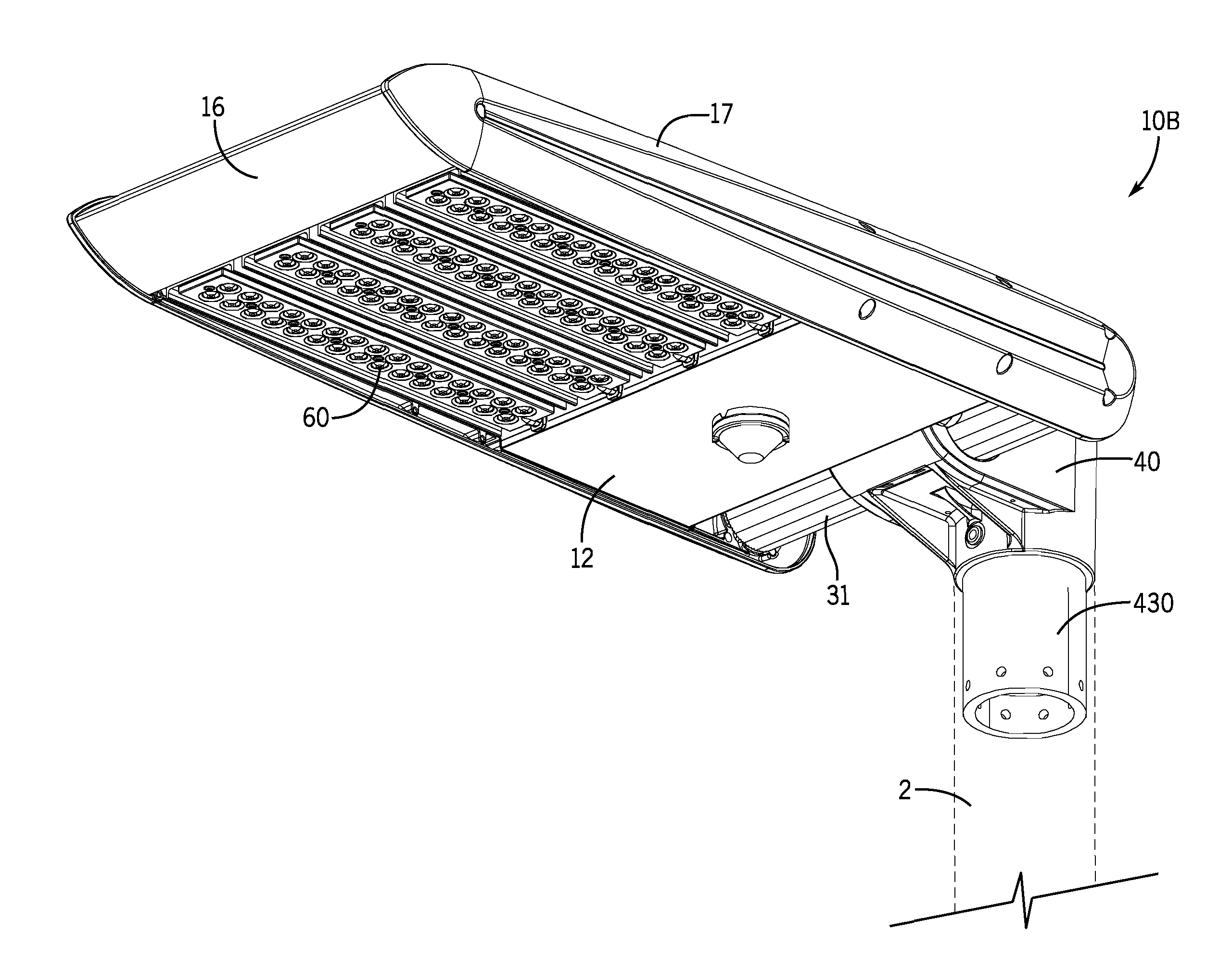
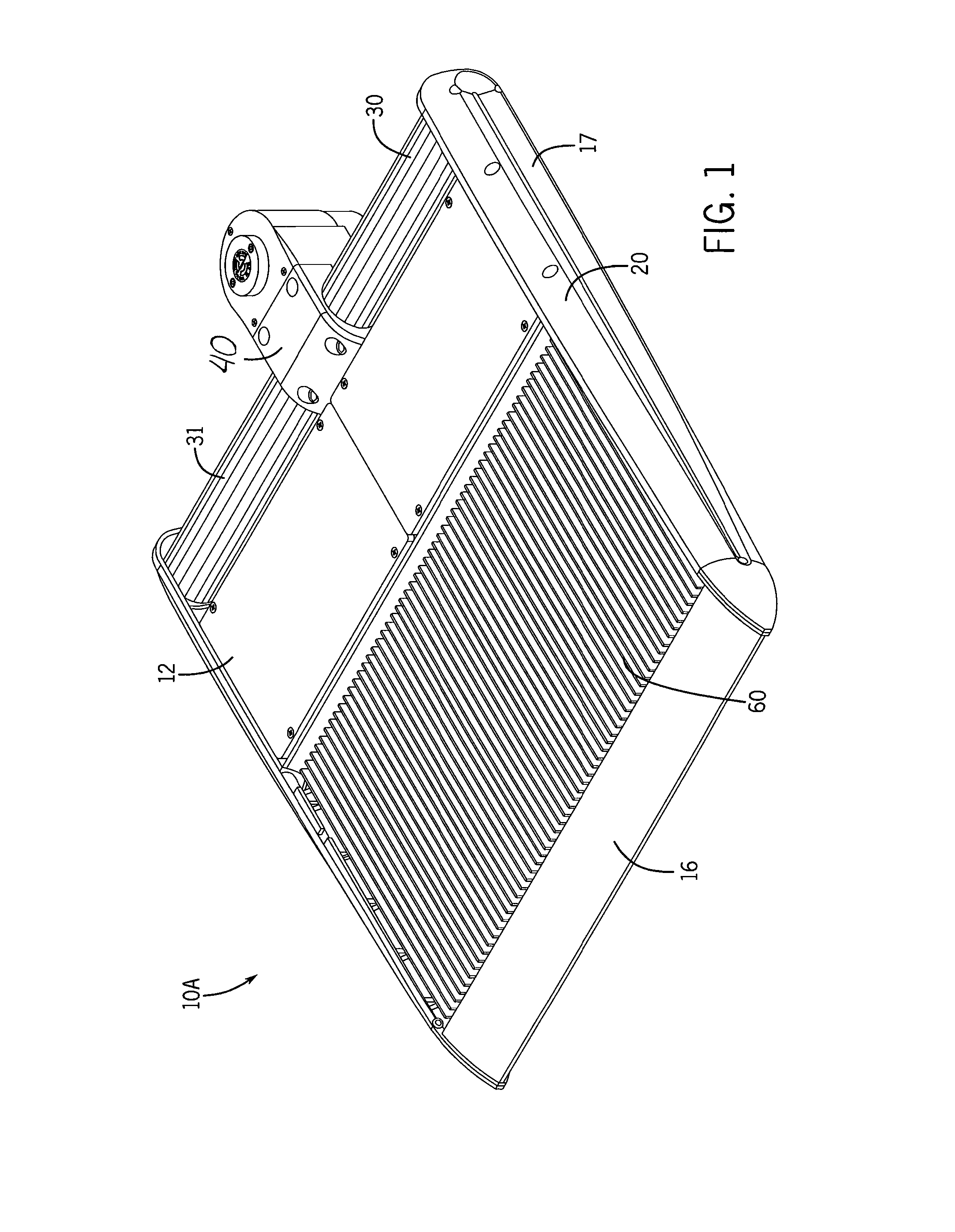
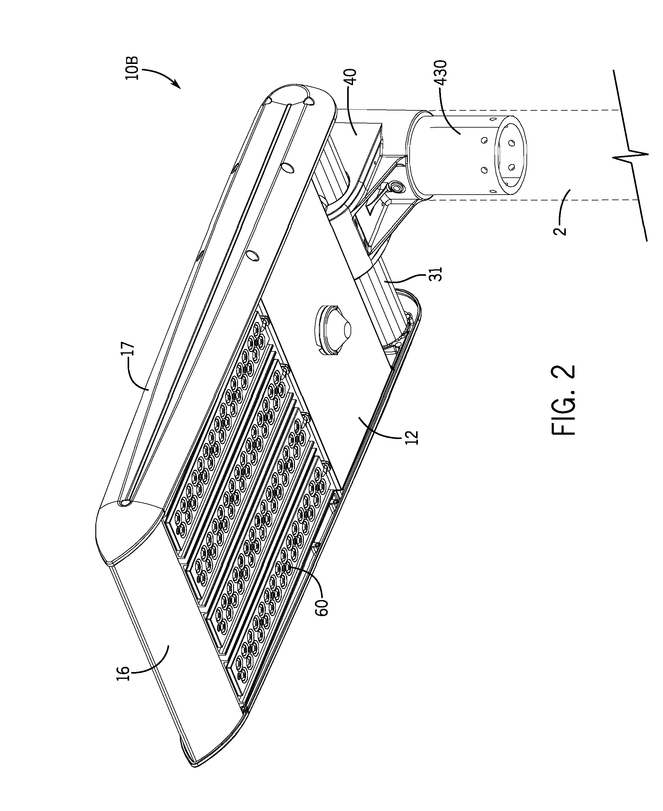
[0113]FIGS. 1-11 illustrate an LED light fixtures 10A and 10B (the latter in FIG. 2 only) in accordance with this invention. Common or similar parts are given the same numbers in the drawings of both embodiments, and the light fixtures are often referred to by the numeral 10, without the A or B lettering used in the drawings, and in the singular for convenience.

[0114]Light fixture 10 includes a main body portion 20 and a mounting assembly 30 for adjustable securement to a static structure. An exemplary static structure is shown in FIG. 2 as a pole 2 atop which fixture 10 may be installed. It should be understood, of course, that the inventive light fixture 10 may be mounted with respect to other static structures such as walls, ceilings, along-ground mounts, free-standing advertizing frames and the like.

[0115]Mounting assembly 30 illustrated in FIGS. 1-10 includes a bar 31 having a gripping region 32 and a gripper 40 attachable to pole 2. As best seen in FIGS. 6-7, gripper 40 grips ...


PUM


Abstract

A mounting assembly for securing a light fixture to a static structure. The mounting assembly includes a bar and a securing member which has a bar-gripping portion and an arm portion extending from the bar-gripping portion and attachable to the static structure. The bar is secured with respect to a main body portion of the light fixture. The bar has an axis. The arm portion has an arm axis which is substantially orthogonal to the bar axis. In another aspect of this invention, the mounting assembly includes a fixture-holding portion and an arm portion secured to the fixture-holding portion. The fixture-holding portion is secured with respect to the light fixture. The arm portion configured for selective attachment to a substantially cylindrical static structure and a substantially planar surface.

Description

RELATED APPLICATION[0001]This application is a continuation-in-part of patent application Ser. No. 13 / 838,479, filed Mar. 15, 2013, which in turn is based in part on U.S. Provisional Application Ser. No. 61 / 624,211, filed Apr. 13, 2012. The contents of application Ser. Nos. 13 / 838,479 and 61 / 624,211 are incorporated herein by reference.FIELD OF THE INVENTION[0002]This invention relates to lighting fixtures and, more particularly, to mounting assemblies for securing light fixtures with respect to static structures.BACKGROUND OF THE INVENTION[0003]Light fixtures such as floodlights are often used for illumination of a selected area or object and typically need to be adjusted into a desired orientation for maximal effect. Adjustable light fixtures are popular with architects, lighting designers and building owners as a way to visually “highlight” certain building and landscape features and improve the nighttime appearance of buildings and grounds.[0004]Large properties may require, e.g...

Claims


Application Information

Patent Timeline
Patent Type & Authority Applications(United States)
IPC IPC(8): F21V21/14
CPCF21V21/14F21S2/005F21S8/086F21V21/00F21V21/26F21V15/013F21V29/00F21V29/004F16B2/06F16B2/10
Inventor HOBSON, CHARLES O.CREASMAN, ETHANGOELZ, DAVID P.
Owner IDEAL IND LIGHTING LLC
Why Eureka
Try Eureka