Analytic estimation apparatus, methods, and systems

an estimation apparatus and azimuth angle technology, applied in seismology for waterlogging, instruments, measurement devices, etc., can solve the problems of increasing the complexity of the polynomial, reducing the execution time, and not indicating analytically minimizing the objective function with respect to the azimuth angl

Active Publication Date: 2014-08-07
HALLIBURTON ENERGY SERVICES INC
View PDF8 Cites 7 Cited by
  • Summary
  • Abstract
  • Description
  • Claims
  • Application Information

AI Technical Summary

Benefits of technology

[0030]The equations are a function of inner products over the sample space. The method described herein may provide insight as to the best numerical search method for minimizing the auxiliary parameters, and may even be used as the basis for algorithms that minimize the objective function with respect to all parameters analytically, so that numerical searching is completely eliminated in some embodiments.
[0049]Given the global minimum of the objective function with respect to angle at a point in the auxiliary parameter space, the most useful method for minimizing the objective function with respect to the auxiliary parameters, δs and s2 (or equivalently s1), is determined by the behavior of the objective function, O(θg(s1, δs), s1, δs), in the (s1, δs) plane as mentioned previously.
[0054]The objective function shown in the graph 1031 is a smooth function with a well-defined minimum, making a numeric search for the value of s1 that minimizes the objective function along this curve easy to implement.
[0070]The signal processor 1130 may be configured to estimate a global minimum of an objective function with respect to an azimuth angle and a set of auxiliary parameters associated with an auxiliary parameter space, said azimuth angle corresponding to an orientation of the transmitter arrays and the receiver arrays relative to fast and slow principal flexural wave axes. The signal processor 1130 may also be configured to estimate said azimuth angle by minimizing the objective function analytically with respect to the azimuth angle at a point in the auxiliary parameter space, said signal processor 1130 to minimize the objective function at said analytically estimated azimuth angle with respect to the set of auxiliary parameters over a domain of the auxiliary parameter space, and to remove existing ambiguities associated with the fast and slow principal flexural wave axes.
[0075]During drilling operations, the drill string 508 (perhaps including the Kelly 516, the drill pipe 518, and the bottom hole assembly 520) may be rotated by the rotary table 410. In addition to, or alternatively, the bottom hole assembly 520 may also be rotated by a motor (e.g., a mud motor) that is located downhole. The drill collars 522 may be used to add weight to the drill bit 526. The drill collars 522 may also operate to stiffen the bottom hole assembly 520, allowing the bottom hole assembly 520 to transfer the added weight to the drill bit 526, and in turn, to assist the drill bit 526 in penetrating the surface 504 and subsurface formations 414.
[0108]Using the apparatus, systems, and methods disclosed herein, those in the petroleum recovery industry and other industries may now be able to more accurately and rapidly assess the properties of geologic formations. Increased operational efficiency and client satisfaction may result.

Problems solved by technology

However, none of these conventional mechanisms suggest analytically minimizing the objective function with respect to the azimuth angle.
Even more exotic objective functions can be used, but these increase the complexity of the polynomial, and correspondingly, the execution time.

Method used


Image

  • Analytic estimation apparatus, methods, and systems
  • Analytic estimation apparatus, methods, and systems
  • Analytic estimation apparatus, methods, and systems

Examples


first example

(a) FIRST EXAMPLE OBJECTIVE FUNCTION

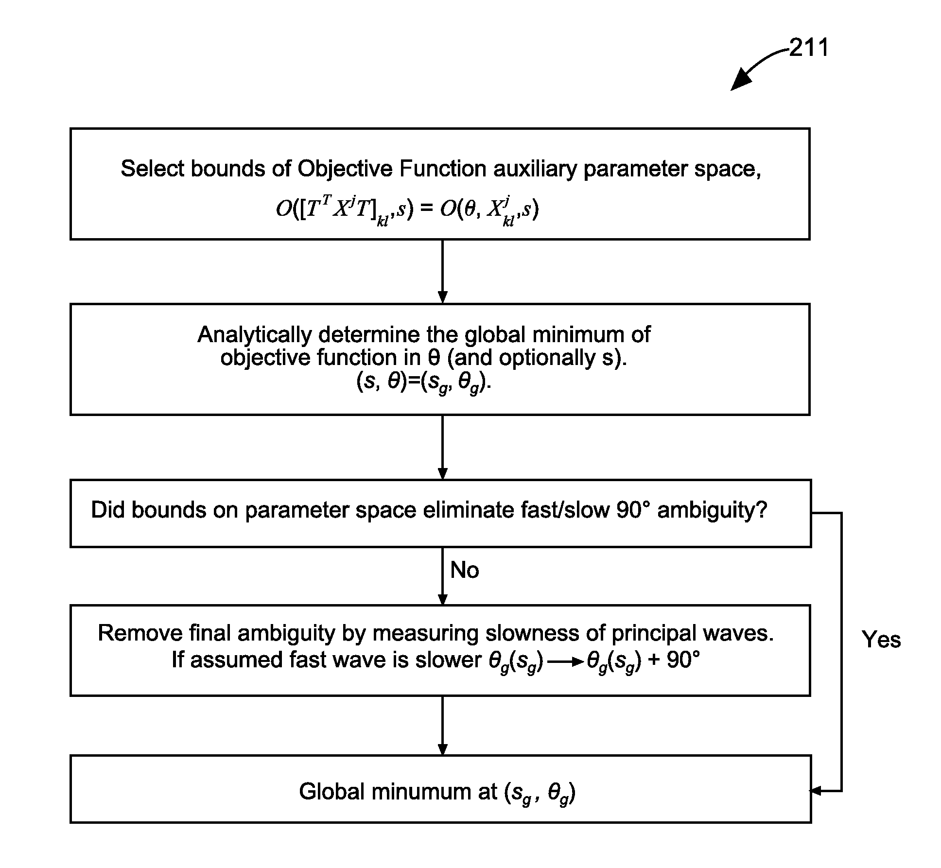
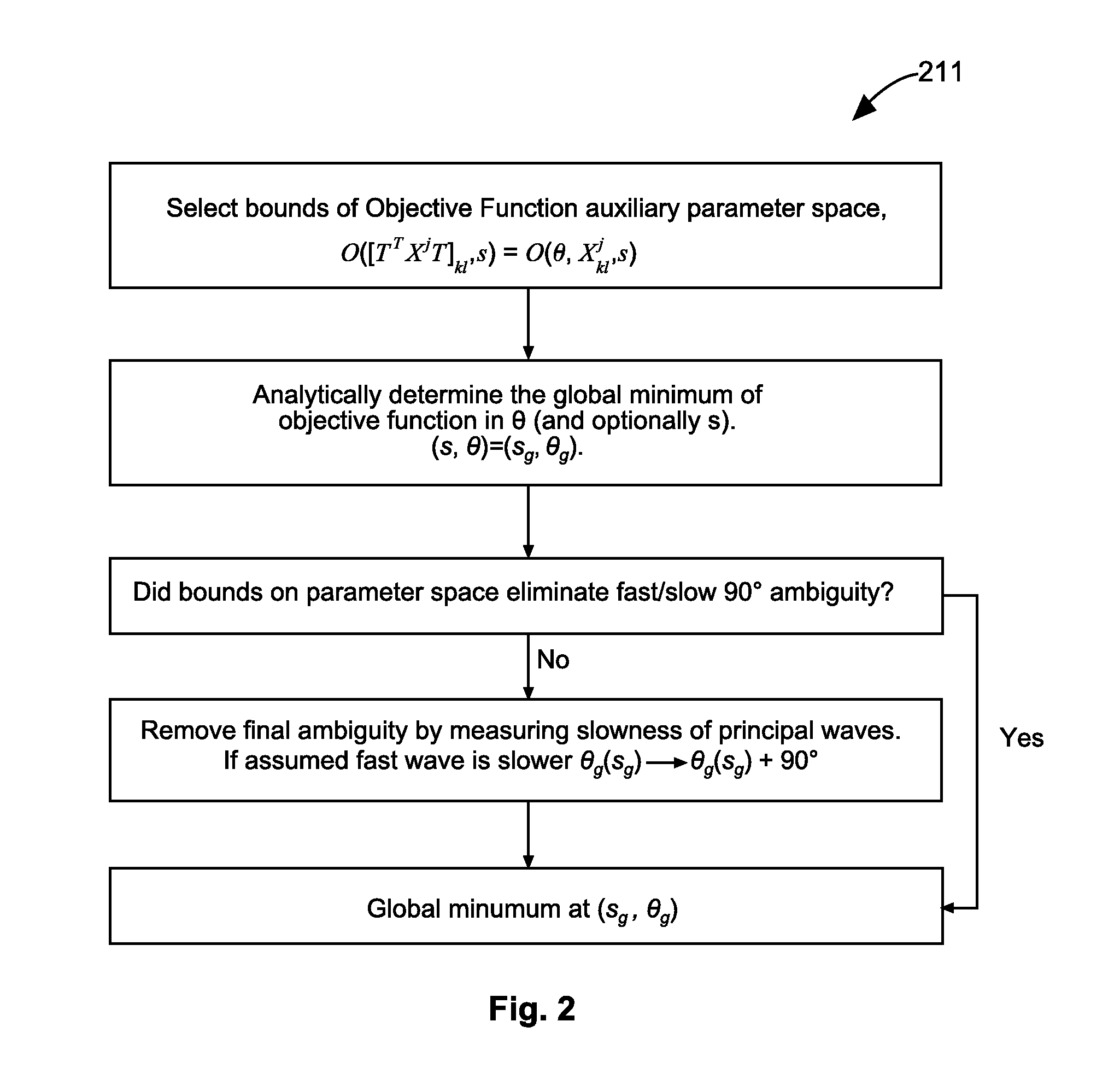
[0024]As an example, consider an embodiment of the objective function specified in U.S. Pat. No. 6,791,899. In the case of a single transmitter ring, N receiver rings, and a single auxiliary parameter, slowness s, the objective function can be expressed in the form of equation (3):

O(θ,s)≡∑m∈{1,…,N}TST≤t≤TST+T[FPest(θ,t,s)-FPm(θ,t+szm)]2,where(3)FPest(θ,t,s)≡1N∑nFPn(θ,t+szn).(4)

[0025]In equations (3) and (4), TSTis the start time of the flexural mode waveform at mid-array, and zm is the position of receiver ring m relative to mid-array. This objective function simply computes the variance of the (1,1) element of equation (2). For the correct choice of the angle θ, the waveform FP will travel at the slowness of the fast principal flexural wave, s1, and the waveforms at each receiver, FPm, will be stationary for s=s1. At this point the objective function (variance) will be a minimum. The objective function will also be a minimum at θ+90° for s=s2, th...

second example

(b) SECOND EXAMPLE OBJECTIVE FUNCTION

[0026]A more complex example is an embodiment of the objective function specified in U.S. Pat. No. 5,712,829. After studying some associated synthetic waveforms, it can be seen that the fast and slow principal waveforms are nearly identical, except for a time shift due to the difference in slowness. This makes it possible to form an objective function using all receiver combinations. In the case of a single transmitter ring, N receiver rings, and two auxiliary parameters, the objective function can be expressed in equation (5) as:

(5)O(θ,δs,s2)∑m,n∈{1,…,N}TST≤t+s1zm≤TST+T{[SPn(θ,t-s2(m-n)δz+δs(zm+z_))-FPm(θ,t)]2+[SPn′(θ,t-s2(m-n)δz+δs(zm+z_))-FPm′(θ,t)]2}.

[0027]In equation (5), δs is the difference in slowness of the principal waves, δs=s2−s1, δz is the receiver element spacing, z is the distance from transmitter to receiver mid-array, and the primed functions are the derivatives with respect to θ of the fast and slow principal waves, such that:

FP...


PUM


Abstract

In some embodiments, apparatus and systems, as well as methods, may operate to record a plurality of acoustic waveforms corresponding to acoustic waves received at azimuthally orthogonal dipole receiver arrays surrounded by a geological formation, the waves being generated by azimuthally orthogonal transmitter arrays. Further activity may include analytically estimating a global minimum of a predefined objective function with respect to an azimuth angle at a point in an auxiliary parameter space associated with a set of auxiliary parameters, minimizing the objective function at the analytically estimated angle with respect to the auxiliary parameters, removing existing ambiguities associated with the fast and slow principal flexural wave axes, and determining at least one property of the geological formation based on the global minimum. Additional apparatus, systems, and methods are disclosed.

Description

RELATED APPLICATIONS[0001]This international application claims priority benefit to U.S. Provisional Patent Application Ser. No. 61 / 533,420, filed Sep. 12, 2011 and U.S. Provisional Patent Application Ser. No. 61 / 533,620, filed Sep. 12, 2011, which are incorporated herein by reference in their entirety.BACKGROUND[0002]Conventional algorithms use only numerical searching for anisotropy processing of cross-dipole acoustic waveforms, to minimize an objective function whose parameters are the azimuth angle of the X-dipole transmitter relative to the fast principal flexural wave axis, and a set of auxiliary parameters. The auxiliary parameters are used to characterize the received waveforms as functions of slowness and borehole radius, among others.BRIEF DESCRIPTION OF THE DRAWINGS[0003]FIG. 1 is an acoustic tool operating according the various embodiments of the invention.[0004]FIG. 2 is a flow chart illustrating anisotropy processing according to various embodiments of the invention.[0...

Claims


Application Information

Patent Timeline
Patent Type & Authority Applications(United States)
IPC IPC(8): G01V1/50
CPCG01V1/50G01V1/36G01V2210/1299G01V2210/27G01V2210/67
Inventor COLLINS, MARK V.CHENG, ARTHUR
Owner HALLIBURTON ENERGY SERVICES INC
Why Eureka
Try Eureka