
Center hole diaphragm mounting of brake chamber for vehicle

Active Publication Date: 2014-08-14
MIRAE VC CO LTD
View PDF10 Cites 0 Cited by
  • Summary
  • Abstract
  • Description
  • Claims
  • Application Information

AI Technical Summary

Benefits of technology

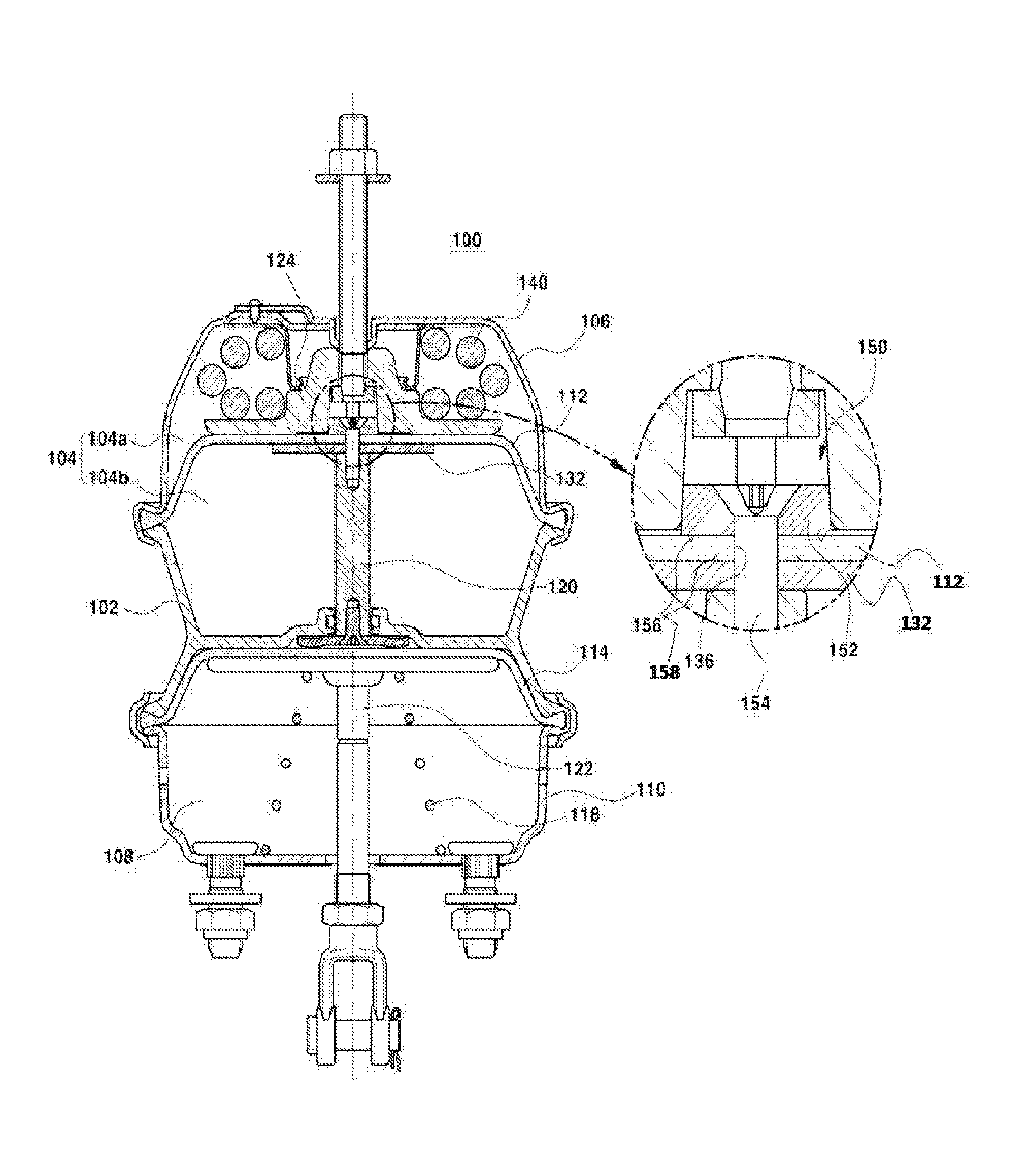
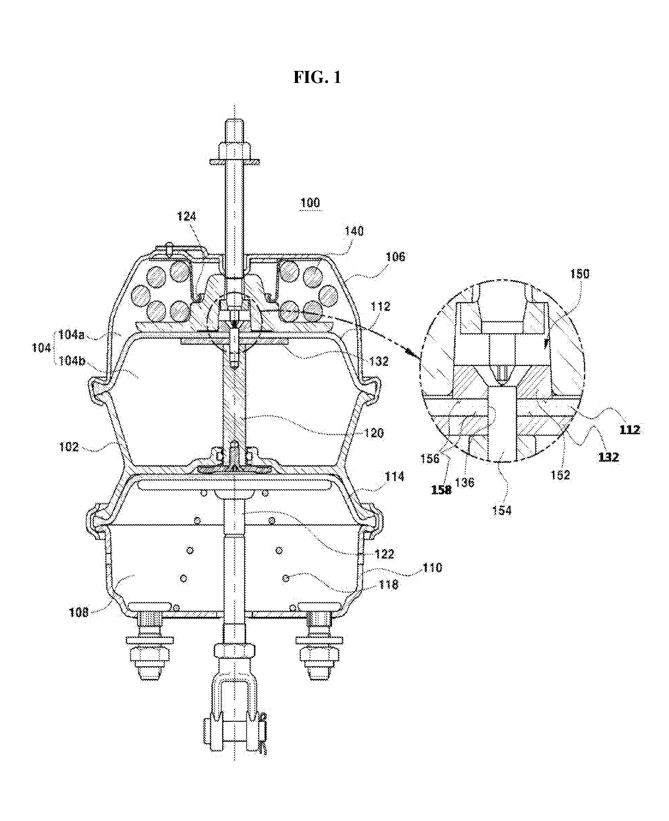
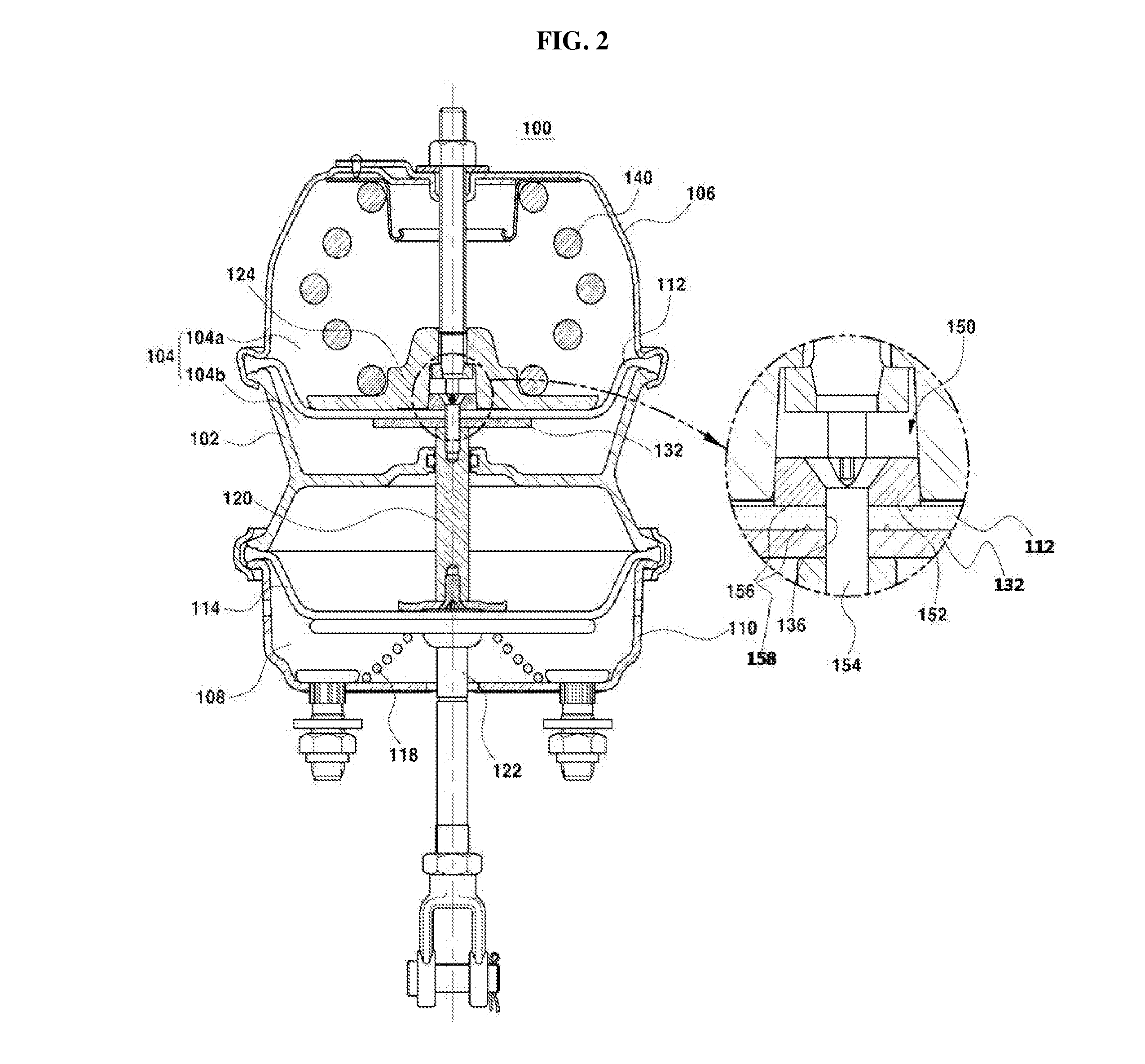
The present disclosure is about integrating a push rod and a piston through a center hole in a spring diaphragm, using a bracket and screw. This results in a restoring force for making upward movement after downward movement, using a power spring. This reduction in parts and manufacturing costs leads to cost savings.

Problems solved by technology

However, since the general spring diaphragm has a closed structure, the return spring guide, the push rod plate, the return spring or the like must be assembled to generate a restoring force for making upward movement after downward movement, which increases the number of parts and manufacture costs.

Method used


Image

  • Center hole diaphragm mounting of brake chamber for vehicle
  • Center hole diaphragm mounting of brake chamber for vehicle
  • Center hole diaphragm mounting of brake chamber for vehicle

Examples


Embodiment Construction

[0025]The present invention now will be described more fully hereinafter with reference to the accompanying drawings, in which embodiments of the invention are shown. This invention may, however, be embodied in many different forms and should not be construed as limited to the embodiments set forth herein. Rather, these embodiments are provided so that this disclosure will be thorough and complete, and will fully convey the scope of the invention to those skilled in the art.

[0026]The terminology used herein is for the purpose of describing particular embodiments only and is not intended to be limiting of the invention. As used herein, the singular forms “a”, “an” and “the” are intended to include the plural forms as well, unless the context clearly indicates otherwise. It will be further understood that the terms “includes”, “comprises” and / or “comprising,” when used in this specification, specify the presence of stated features, integers, steps, operations, elements, and / or compone...


PUM


Abstract

Provided is a diaphragm mounting of a brake chamber for a vehicle, and in particular, to a diaphragm mounting of a brake chamber for a vehicle, which may exclude a return spring for restoring a diaphragm to an original position. The diaphragm mounting of a brake chamber for a vehicle includes a spring diaphragm assembled between a head and a flange case, a push rod having a top surface closely adhered to a bottom surface of the spring diaphragm, a piston located between the head and the spring diaphragm, and a power spring disposed between a top surface of the piston and a bottom surface of the head to pressurize the piston with an elastic force, wherein a center hole is formed at the center of the spring diaphragm, and the push rod located below the spring diaphragm and the piston located above the spring diaphragm are integrally connected by a coupling unit through the center hole.

Description

CROSS-REFERENCE TO RELATED APPLICATION[0001]This application claims priority of Korean Patent Application No. 10-2013-0014848, filed on Feb. 12, 2013, and priority of Korean Patent Application No. 10-2014-0014937, filed on February 10, 2014, in the KIPO (Korean Intellectual Property Office), the disclosure of which is incorporated herein by reference.BACKGROUND OF THE INVENTION[0002]1. Field of the Invention[0003]The following disclosure relates to a diaphragm mounting of a brake chamber for a vehicle, and in particular, to a diaphragm mounting of a brake chamber for a vehicle, which may exclude a return spring for restoring a diaphragm to an original position.[0004]2. Description of the Related Art[0005]As well known in the art, a brake system of a commercial vehicle employs an air brake with an excellent braking force and a convenient handling property, and a brake chamber included in the air brake system is classified into spring types, piston types or the like.[0006]If a brake p...

Claims


Application Information

Patent Timeline
IPC IPC(8): B60T13/26
CPCB60T13/261B60T17/083
Inventor PARK, HAN JOO
Owner MIRAE VC CO LTD
Learn More