Pneumatic tire

a pneumatic tire and tire body technology, applied in the field of pneumatic tires, can solve the problems reduced friction force and pattern rigidity, and increased risk of deterioration of uneven wear resistance, so as to improve uneven wear resistance and drainage performance on wet roads, good balance

Active Publication Date: 2014-08-21
SUMITOMO RUBBER IND LTD
View PDF6 Cites 15 Cited by
  • Summary
  • Abstract
  • Description
  • Claims
  • Application Information

AI Technical Summary

Benefits of technology

[0007]It is therefore, an object of the present invention to provide a pneumatic tire, in which, by providing a specific configuration for notch which are formed in a central land portion to extend from a crown main groove, running performance on icy roads, uneven wear resistance and drainage performance on wet roads are improved in a good balance.

Problems solved by technology

In such technique, however, as the land portions are decreased in the ground contacting area, frictional force and pattern rigidity are decreased, and running performance on icy roads and uneven wear resistance are liable to deteriorate.Patent document 1: JP-A-2010-149599Patent document 2: JP-A-2009-214775

Method used


Image

  • Pneumatic tire
  • Pneumatic tire
  • Pneumatic tire

Examples


first embodiment

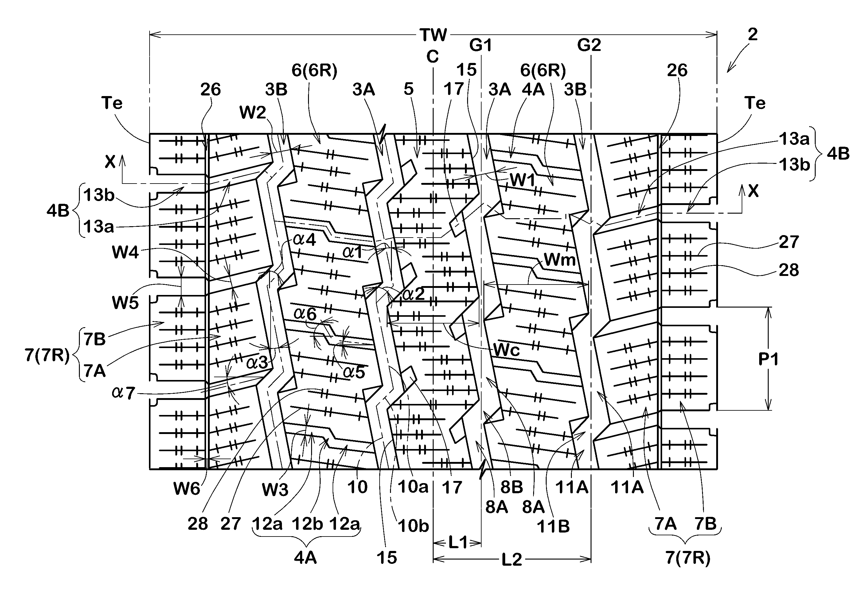
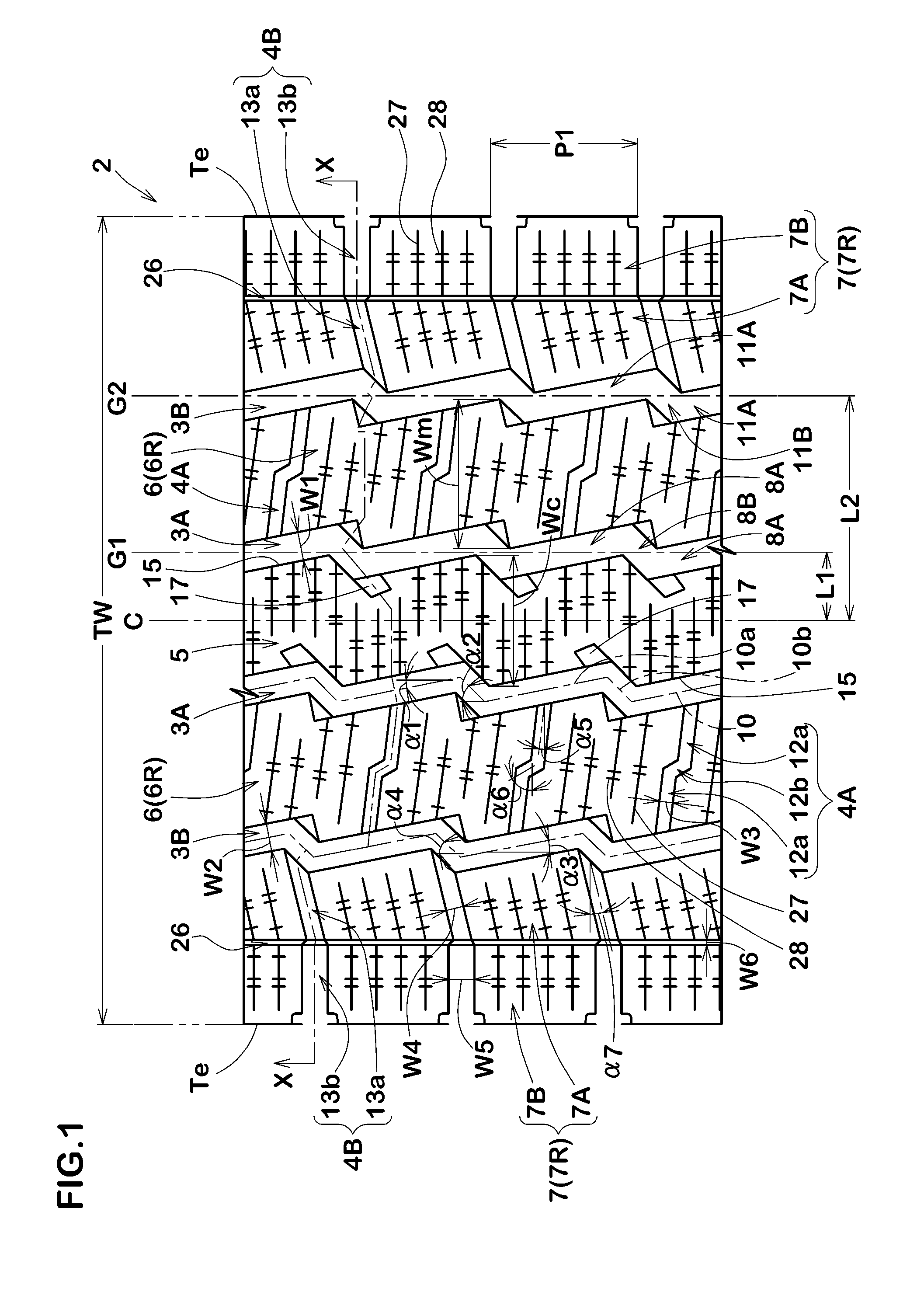
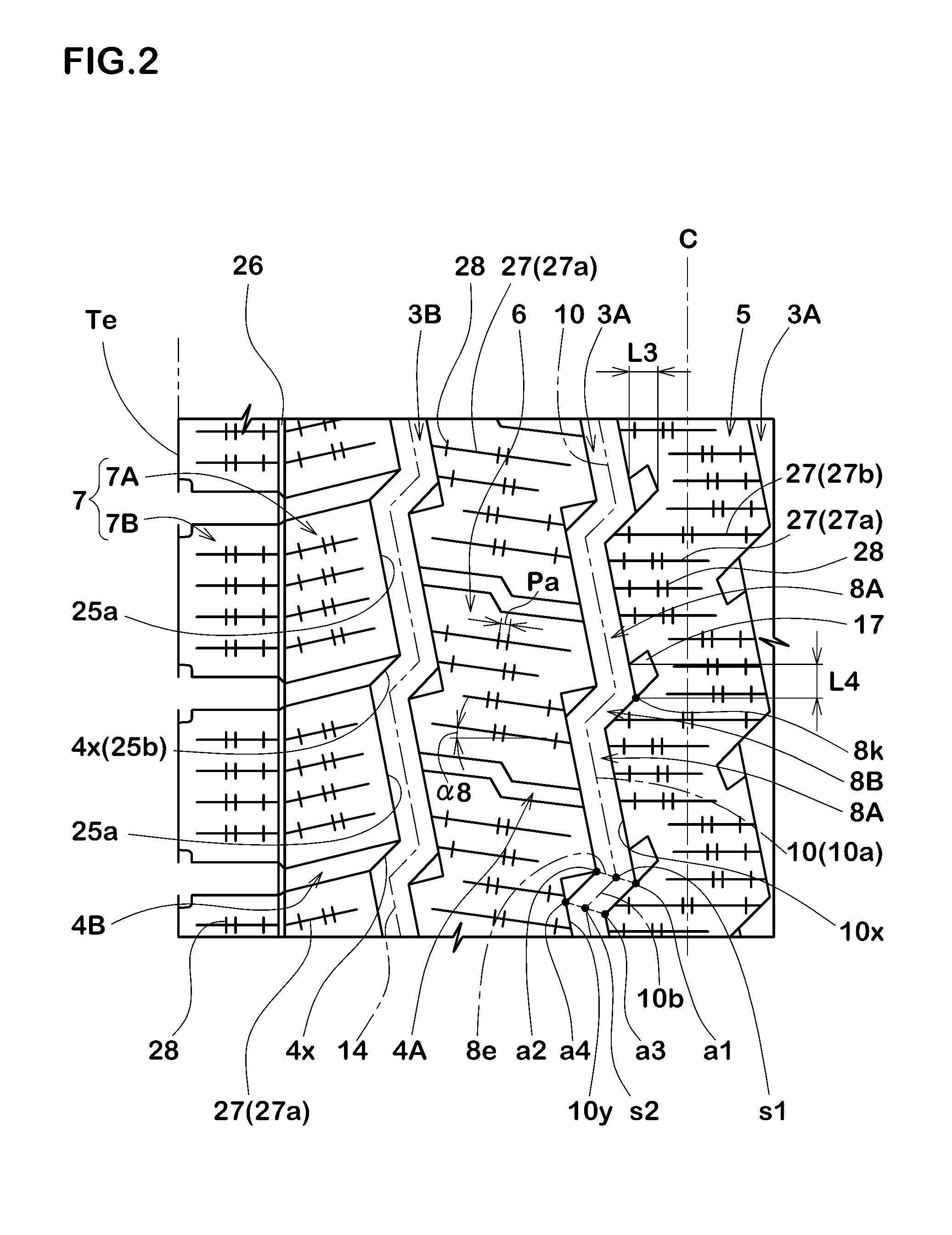
[0042]FIGS. 1-4 show a first embodiment of the present invention, and FIG. 5 shows a modification thereof.

[0043]In the first embodiment, the crown main grooves 3A are a zigzag groove made up of long groove segments 8A and short groove segments 8B which are arranged alternately in the tire circumferential direction. Since the edges of such crown main groove 3A include an axial component, the drive power and braking force become increased, and accordingly, running performance on icy roads can be improved.

[0044]The long groove segments 8A and the short groove segments 8B of each of the crown main grooves 3A are inclined with respect to the tire circumferential direction such that the widthwise center lines 10a of the long groove segments 8A are inclined in one direction (in FIG. 1, a left side upward inclination), and

the widthwise center lines 10b of the short groove segments 8B are inclined in one direction opposite to that of the long groove segments 8A (in FIG. 1, a right side upwar...

second embodiment

[0158]FIGS. 6-8 show a second embodiment of the present invention, and FIG. 9 shows a modification thereof.

[0159]In the second embodiment, the crown main grooves 3A are a zigzag groove made up of long groove segments 8A and short groove segments 8B which are arranged alternately in the tire circumferential direction. Since the edges of such crown main groove 3A include an axial component, the drive power and braking force become increased, and accordingly, running performance on icy roads can be improved.

[0160]The long groove segments 8A and the short groove segments 8B of each of the crown main grooves 3A are inclined with respect to the tire circumferential direction such that the widthwise center lines 10a of the long groove segments 8A are inclined in one direction (in FIG. 6, a left side upward inclination), and the widthwise center lines 10b of the short groove segments 8B are inclined in one direction opposite to that of the long groove segments 8A (in FIG. 61, a right side u...


PUM


Abstract

A pneumatic tire is provided in the tread portion with a central land portion between two crown main grooves. The central land portion is provided with notches each having a depth of 55% to 65% of the depth of the crown main groove and having a closed end and an open end opening to the crown main groove.
The maximum axial length of the central notch is 10% to 15% of the maximum axial length of the central land portion, and the circumferential length of the opening is 10% to 15% of one circumferential pitch of the shoulder block row 7R.
The circumferential length of the opening is 15% to 25% of one circumferential pitch of the central notches.

Description

BACKGROUND OF THE INVENTION[0001]The present invention relates to a pneumatic tire, more particularly to a tread pattern capable of improving running performance on icy roads, drainage performance on wet roads and uneven wear resistance in a good balance.[0002]Winter tires or pneumatic tires for the winter season are required to have running performance on icy roads and drainage performance on wet roads which are improved in a good balance at high levels.[0003]For example, in the following patent documents, it is proposed to increase the widths of tread grooves such as circumferential grooves and axial grooves in order to improve drainage performance on wet roads.[0004]In such technique, however, as the land portions are decreased in the ground contacting area, frictional force and pattern rigidity are decreased, and running performance on icy roads and uneven wear resistance are liable to deteriorate.[0005]Patent document 1: JP-A-2010-149599[0006]Patent document 2: JP-A-2009-214775...

Claims


Application Information

Patent Timeline
Patent Type & Authority Applications(United States)
IPC IPC(8): B60C11/12
CPCB60C11/1259B60C11/0304B60C11/0306B60C11/033B60C2011/0346B60C2011/0348B60C2011/0353B60C2011/0355B60C2011/0383B60C2011/0388B60C2011/1209B60C2011/1213
Inventor TAGASHIRA, MASAONAKAYAMA, HIROYUKI
Owner SUMITOMO RUBBER IND LTD
Why Eureka
Try Eureka