Unlock instant, AI-driven research and patent intelligence for your innovation.

Package Assembly with Tear Away Film and Manufacturing System

Inactive Publication Date: 2014-08-21
DELKOR SYST
View PDF18 Cites 15 Cited by
  • Summary
  • Abstract
  • Description
  • Claims
  • Application Information

AI Technical Summary

Benefits of technology

This patent is about a package assembly that includes multiple containers wrapped in heat-shrink wrapping. The heat-shrink wrapping has perforations and a tear strip between them. The perforations are arranged in two pathways that meet at a hole in the wrapping. The heat-shrink wrapping can also have chads attached to it. The method of making the package assembly involves wrapping the containers with the heat-shrink wrapping, perforating it, and applying heat to shrink it around the containers. The first and second pathways create a tear strip. The patent also describes a heat-shrink wrapping dispenser and a perforating assembly for making the package assembly. The perforating assembly includes a die member and a cutting member that works in conjunction with the die member. The cutting member has a die-facing perimeter with a cutting portion and a non-cutting portion. The cutting member can also have cutting teeth along its perimeter. The technical effect of this patent is improved protection and preservation of the package contents through the use of heat-shrink wrapping with perforations and a tear strip.

Problems solved by technology

One such disadvantage is that the heat-shrink wrapping can be difficult to remove once transit of the containers is complete.
In these stores, the clerks, stockroom workers, and floor employees are not allowed to carry cutting devices, making removal of the heat-shrink wrapping even more cumbersome.
An additional drawback of heat-shrink wrapping is that it has a tendency to prevent cooling of the contents within the heat-shrink wrapping.
In particular, heat from the packaging assembly can become trapped within the heat-shrink wrapping which, in some cases, can negatively impact the contents within the containers.

Method used


Image

  • Package Assembly with Tear Away Film and Manufacturing System
  • Package Assembly with Tear Away Film and Manufacturing System
  • Package Assembly with Tear Away Film and Manufacturing System

Examples


Embodiment Construction

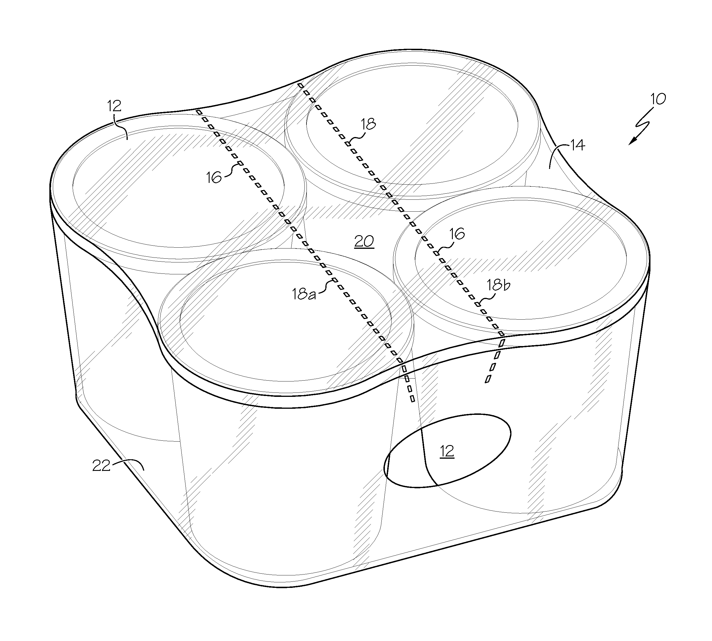
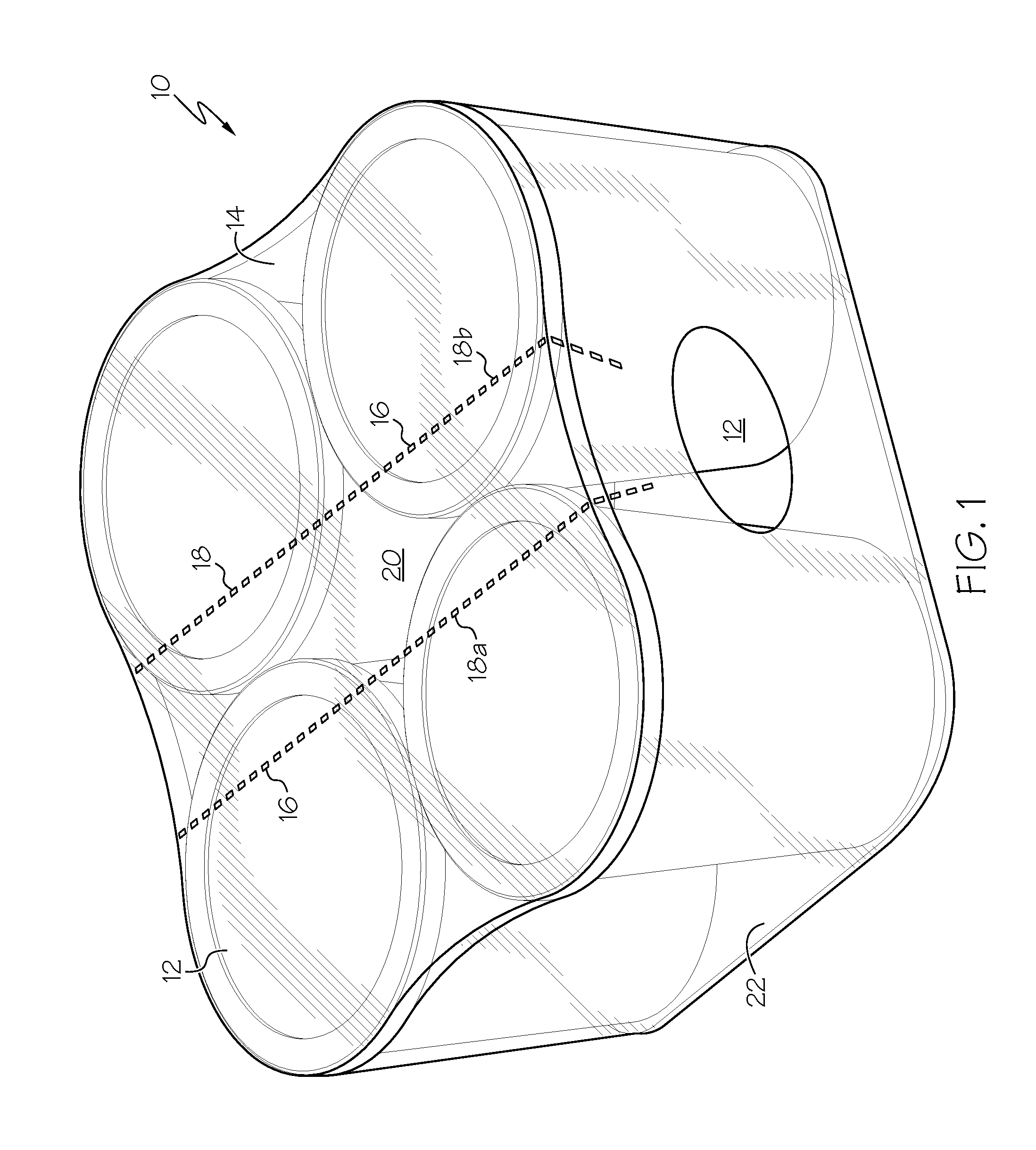
[0032]In order to reduce, or overcome, the problems associated with traditional packaging methods, apparatus, and assemblies, a new package assembly, method of producing the package assembly, and packaging apparatus are herein disclosed. Each is described, in turn, in the following description.

Package Assembly

[0033]With regard to FIG. 1, a package assembly 10 is shown. The package assembly includes a plurality of containers 12 and a film or heat-shrink wrapping 14. The containers 12 can be of any desirable shape or configuration, for example cylindrical, conical, frusto-conical, spherical, cuboid, pyramidal, and combinations thereof. Additional examples of suitable packaging configurations can be found in U.S. Pat. Nos. 7,604,114 to Gessler, 7,392,905 to Andersen, 7,370,761 to Andersen, 6,588,594 to Andersen, 5,887,717 to Anderson, and 7,467,504 to Mate, the contents of each of which are herein incorporated by reference in their entirety.

[0034]In addition to the foregoing, the heat-...


PUM

PropertyMeasurementUnit
Shapeaaaaaaaaaa

Abstract

A package assembly includes a number of containers, a heat-shrink wrapping disposed around the containers and tear strip; the tear strip aids in opening the heat-shrink wrapping. The tear strip can be defined by perforations disposed through the heat-shrink wrapping and arranged in pathways. The perforations are cut in the heat-shrink wrapping with a packaging apparatus having a cutting member. The cutting member is used in combination with a die to leave a chad attached to heat-shrink wrapping. Thereafter, the heat-shrink wrapping is shrunk with a heating source in order to bundle containers together within the package assembly.

Description

CROSS-REFERENCE TO RELATED APPLICATIONS[0001]This Application claims the benefit of and priority to U.S. Provisional Application No. 61 / 765,232, filed Feb. 15, 2013.STATEMENT REGARDING FEDERALLY SPONSORED RESEARCH[0002]Not Applicable.BACKGROUND OF THE INVENTION[0003]In order to bundle containers together for shipment and storage, the containers are oftentimes bundled together in various ways. One way in which containers are bundled together is via the use of a heat-shrink wrapping, which is subsequently heated. In this way, the containers are containers are held in a stable configuration.[0004]The heat-shrink wrapping has certain disadvantages, however. One such disadvantage is that the heat-shrink wrapping can be difficult to remove once transit of the containers is complete. Removal of the heat-shrink wrapping can require tugging and tearing of the heat-shrink wrapping, or cutting it with a knife, scissors, or other sharp utensil. For the end-user of the product, this can be an on...

Claims


Application Information

Patent Timeline
IPC IPC(8): B65D75/52B65B53/02
CPCB65B53/02B65D75/527B65B9/026B65B53/063B65B61/02B65D71/08B65D2571/00567B65D2571/00679
Inventor ANDERSEN, DALE C.WEISS, KEVIN B.
Owner DELKOR SYST