Method for generating 3D mesh from 3D points by using shrink-wrapping scheme of boundary cells

a boundary cell and mesh generation technology, applied in the field of 3d mesh generation, can solve the problems of difficult to obtain a stable model in constituting a 3d surface, conventional mesh generation methods can be applied to a spherical shape, and cannot be applied to the case in which an object is present, so as to reduce the elapsed time for surface modeling

Inactive Publication Date: 2005-06-23
ELECTRONICS & TELECOMM RES INST
View PDF4 Cites 26 Cited by
  • Summary
  • Abstract
  • Description
  • Claims
  • Application Information

AI Technical Summary

Benefits of technology

[0012] It is an object of the present -invention to provide a method for generating a 3D mesh in which original object surface is stab...

Problems solved by technology

In general, it is, however, difficult to obtain a stable model in constituting a 3D surface from the unorganized 3D points since no information on the shape of an object can be obtained except for co...

Method used


Image

  • Method for generating 3D mesh from 3D points by using shrink-wrapping scheme of boundary cells
  • Method for generating 3D mesh from 3D points by using shrink-wrapping scheme of boundary cells
  • Method for generating 3D mesh from 3D points by using shrink-wrapping scheme of boundary cells

Examples


Embodiment Construction

[0019] Reference will now be made in detail to the preferred embodiments of the present invention, examples of which are illustrated in the accompanying drawings.

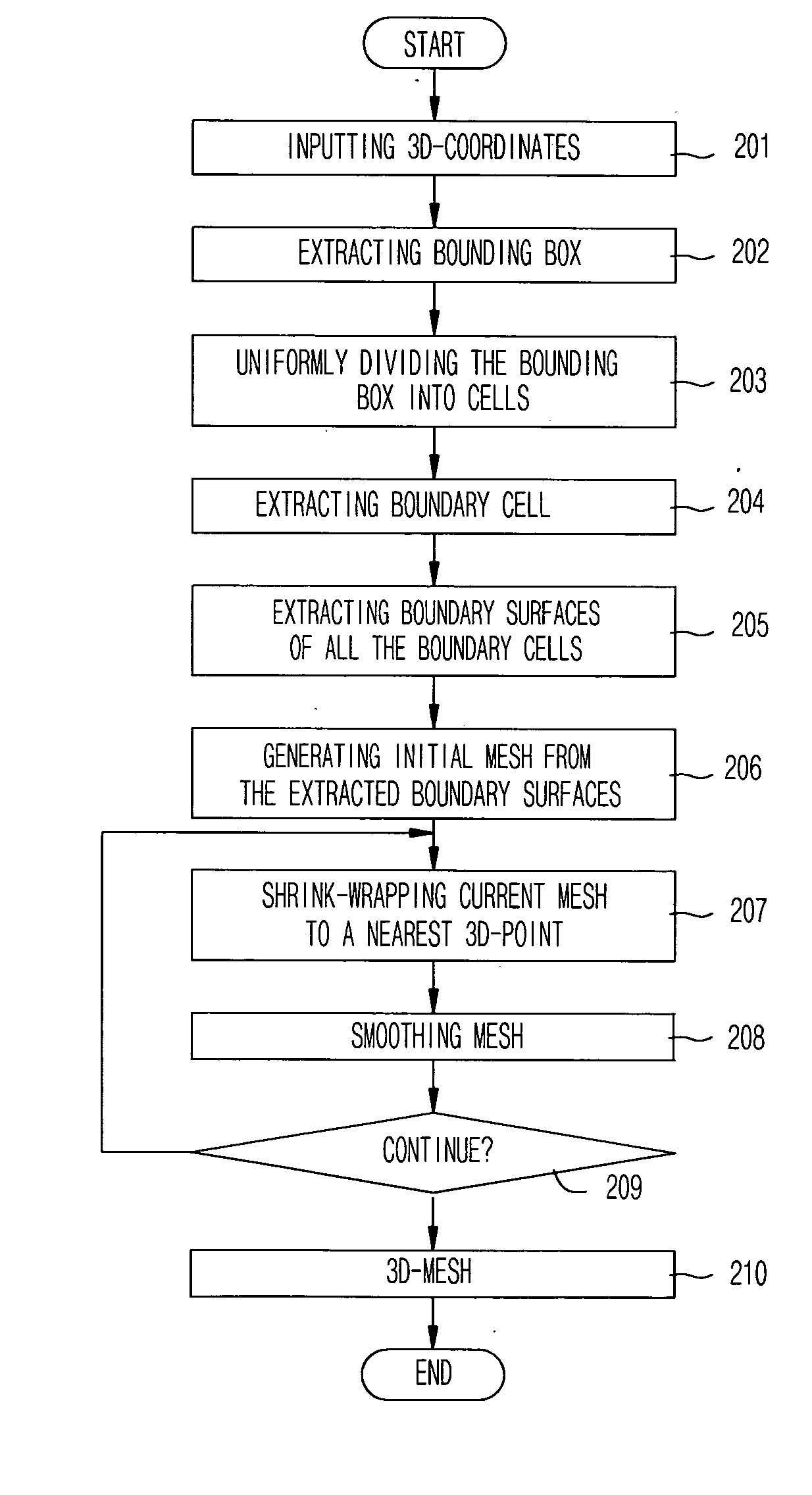
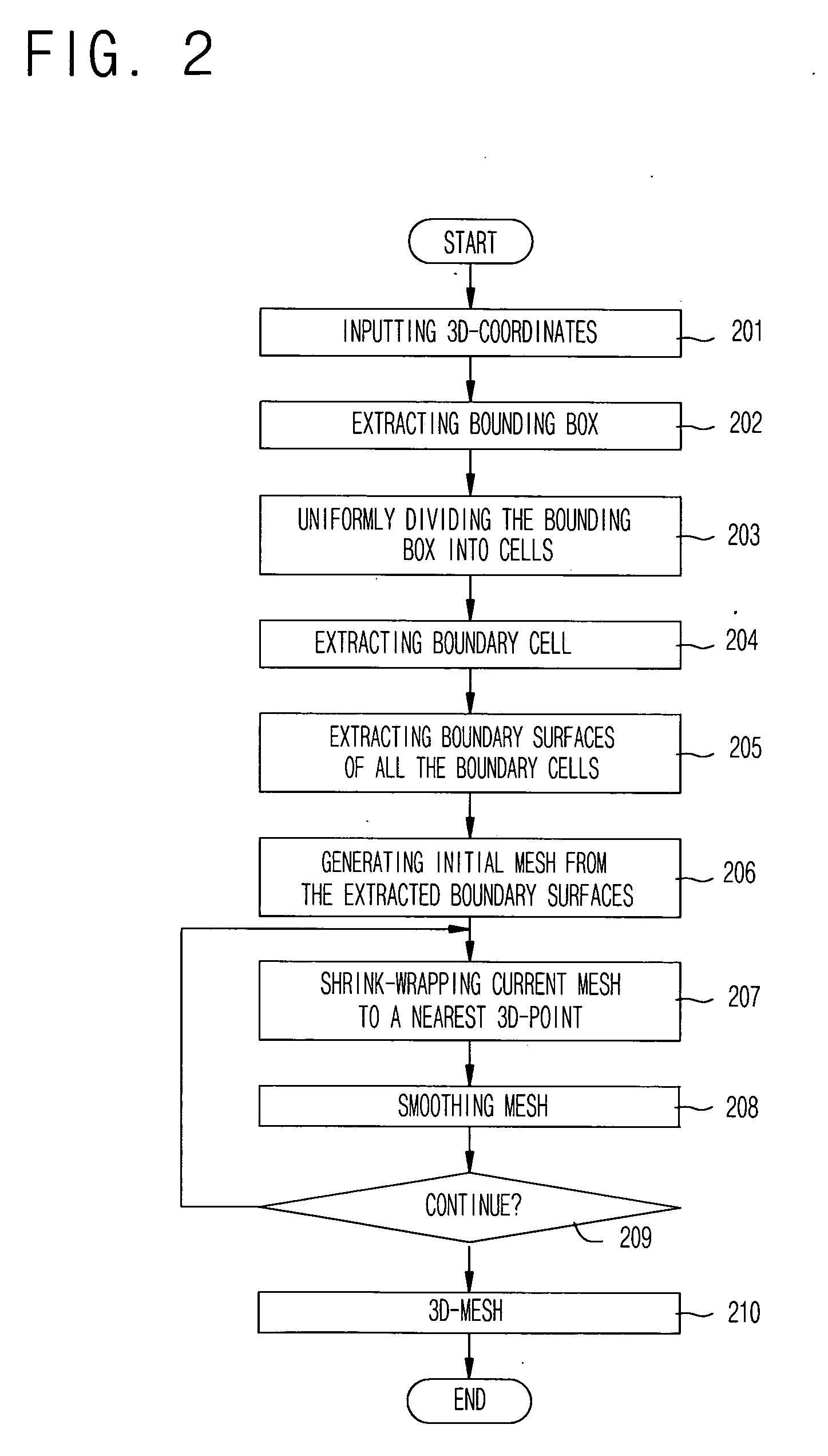
[0020]FIG. 2 is a flowchart of a method for generating a 3D mesh from 3D points by using a shrink-wrapping scheme of boundary cells according to an embodiment of the-present invention.

[0021] When 3D mesh generation method starts, unorganized 3D coordinates extracted by a 3D scanner or a digitizer is inputted (201). A minimum bounding box including all the points is extracted (202). To extract the bounding box, the maximum and minimum values maxx, minx, maxy, miny, maxz, and minz is obtained with respect to all the inputted 3D coordinates in the directions x, y and z. A bounding box is extracted using six faces (x=minx, x=maxx, etc. 2 faces in the direction of each coordinate) according to equation 1.

minxx

minyy

minzz   Equation 1

[0022] Then, the extracted box is uniformly divided into cells of a predetermined size (203)...


PUM


Abstract

The present invention relates to a method for generating a mesh model representing a 3D surface from unorganized 3D points extracted from a 3D scanner by using a shrink-wrapping scheme of boundary cells. A method for generating 3-dimensional mesh according to the present invention comprises the steps of: (a) receiving unorganized 3D point coordinates extracted by a 3D scanner or a digitizer; (b) extracting a minimum bounding box including all the point coordinates and uniformly dividing the extracted bounding box into cells of a predetermined size; (c) extracting a boundary cell including at least one point from the cells, extracting a boundary surface from all the boundary cells, and generating an initial mesh by summing extracted boundary surfaces; (d) calculating distances between each vertex constituting the mesh and the several points, finding a nearest point, and moving the vertex to the nearest point; and (e) averaging location of each shrink-wrapped vertex and location of the neighboring vertexes, and moving the shrink-wrapped vertex to center of neighboring vertexes.

Description

BACKGROUND OF THE INVENTION [0001] 1. Field of the Invention [0002] The present invention relates to a method for generating a 3-dimensional (hereinafter, referred to as 3D) mesh, and more particularly, to a method for generating a mesh model representing a 3D surface from unorganized 3D points extracted from a 3D scanner by using a shrink-wrapping scheme of boundary cells. [0003] 2. Description of the Related Art [0004] The unorganized 3D points do not mean a case in which there is a specific relation between points as range image or contour, but mean a case in which there is not any relation with points as the 3D points data extracted by a 3D digitizer. If a point has a specific relation with points as a range image or a contour, a surface mesh approximating the points can be created using the relation between the points. Currently, various methods have been suggested. In general, it is, however, difficult to obtain a stable model in constituting a 3D surface from the unorganized ...

Claims


Application Information

Patent Timeline
IPC IPC(8): G06T17/00G06T17/20
CPCG06T2210/56G06T17/20G06T17/00
Inventor KOO, BON KICHU, CHANG WOOKIM, JAE CHULCHOI, BYOUNG TAECHOI, YOUNG KYU
Owner ELECTRONICS & TELECOMM RES INST
Why Eureka
Try Eureka