Mounting apparatus

a technology of mounting apparatus and mounting bracket, which is applied in the direction of electrical apparatus casing/cabinet/drawer, machine support, television system, etc., can solve the problems of inconvenient tilting or pivoting of the access mechanism, inability to remove the computer unit mounted in the device, and inability to be convenient, so as to increase the lateral width and be more discrete and secure

Inactive Publication Date: 2014-08-21
PIIXL TECH
View PDF16 Cites 6 Cited by
  • Summary
  • Abstract
  • Description
  • Claims
  • Application Information

AI Technical Summary

Benefits of technology

[0014]The mounting apparatus of the invention also ensures that the enclosure/device can effectively be hidden behind the flat panel, making it more discrete and secure whilst also reducing the need for cabling and specific building work to accommodate the enclosure device separately to the flat panel display.
[0015]It is expected that the mounting apparatus will generally be configured to allow sliding of a device/enclosure horizontally, i.e. so it is accessible at the vertical side edges of a mounted rectangular display. However, in alternative forms the bracket may allow for devices to extend in other directions, e.g. for accessibility at a top or bottom peripheral edge of a display. Indeed, a mounting apparatus according to the invention could be configured to receive and enable sliding of a d

Problems solved by technology

Indeed, the computer unit mounted in the device cannot be removed without clear access to the rear of the display/monitor; which would not be possible if the display were wall mounted.
EP2391194 also describes a rack module for mounting a computer unit behind a flat panel display, where it may pivot to become accessible to a user at a locat

Method used


Image

  • Mounting apparatus
  • Mounting apparatus
  • Mounting apparatus

Examples


Embodiment Construction

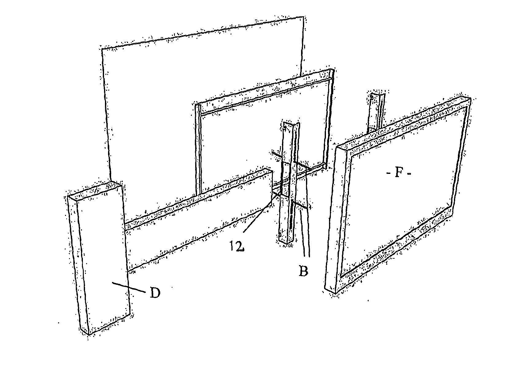
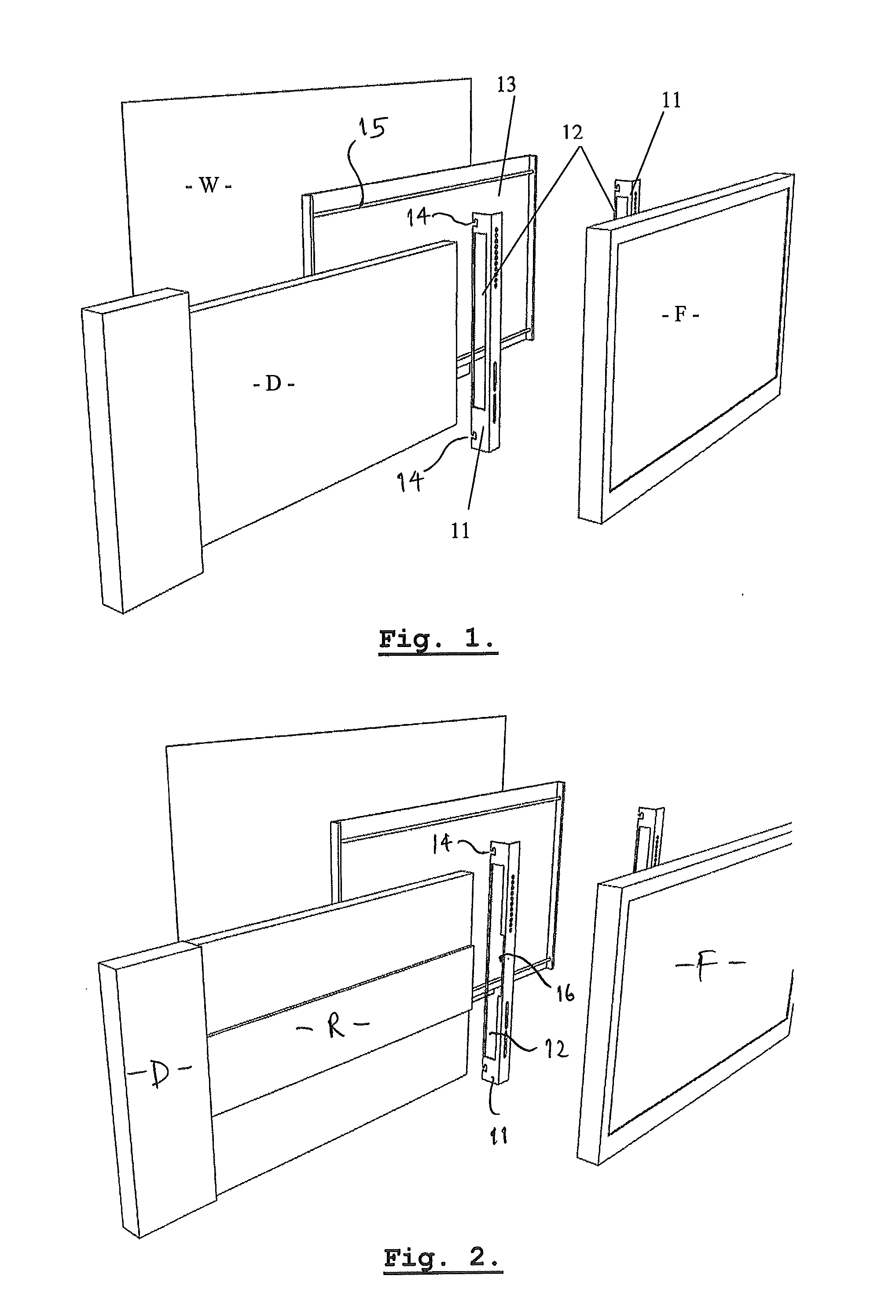
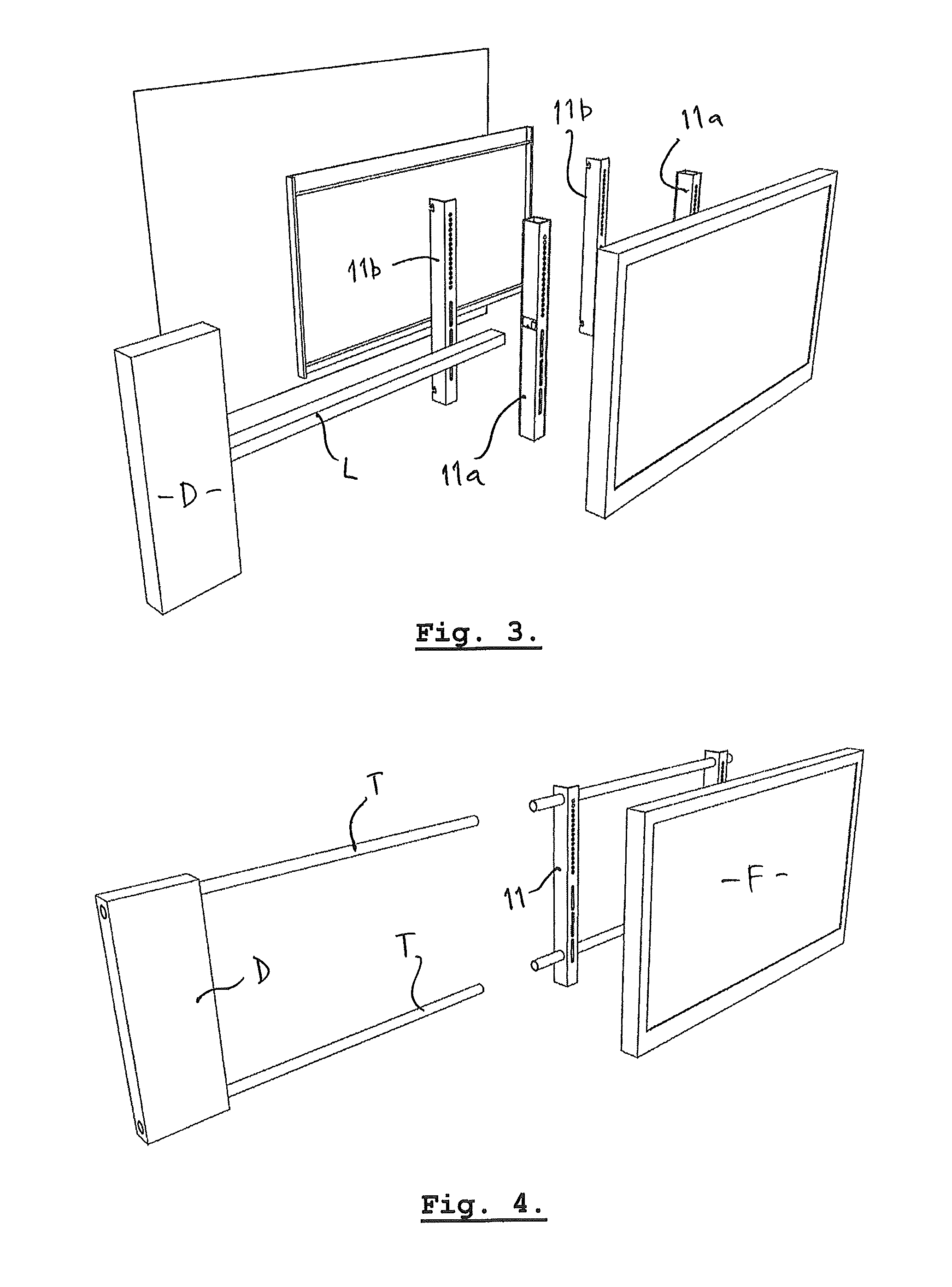
[0025]FIG. 1 illustrates a mounting apparatus according to the invention that comprises two mounting brackets 11 configured to receive, through openings or apertures 12, a peripheral device D or other similar enclosure or media related product.

[0026]In use of the apparatus as illustrated, mounting brackets 11 are firstly fastened to the rear of a flat panel display F, utilising a VESA pattern of fastener spacings, and secondly arranged on a wall mounted frame 13 that is screwed or otherwise affixed to a wall W. In the illustrated form, brackets 11 include hook-like channels 14 that receive rods 15 which span across the frame 13. However, it will be appreciated that a variety of means could be utilised to connect the brackets to the wall frame in a permanent or detachable way. Indeed, the frame (13) could alternatively be mounted on the rear of the display F, with brackets 11 permanently fastened to a wall. In this configuration the display would be removable, leaving the peripheral ...


PUM


Abstract

A mounting apparatus including a bracket (11) for mounting behind a flat panel display (F). The bracket is able to receive a separate device (e.g. a PC enclosure of other electronic components), such that said device can be slidable and accessible from behind the flat panel display when it is mounted thereto.

Description

[0001]The present invention relates to a mounting apparatus, particularly for wall mounting a flat panel display, wherein an enclosure or device can be located behind the display.BACKGROUND TO THE INVENTION[0002]Modern flat panel displays are common for entertainment or computer applications and, as a consequence, an internationally recognised standard has been implemented to provide guidelines for mounting these devices. The VESA-FDMI (Video Electronics Standards Association—Flat Display Mounting Interface) Standard lists a range of square / rectangular screw patterns that may be applied to wall or other mounting devices.[0003]Flat panel displays as used with built-in television receivers or for computer monitoring can be mounted to a wall surface with suitable hanging arrangements that utilise the VESA pattern. Other common devices allow for a flat panel display to be mounted for swivel movement by use of an arm extending from a wall mounting plate.[0004]However, a need has also bee...

Claims


Application Information

Patent Timeline
IPC IPC(8): H05K7/18F16M13/02F16M11/00
CPCH05K7/18F16M13/022F16M11/00G06F1/1607H04N5/64F16M11/22F16M13/02H05K5/0204
Inventor GARDES, FRANCOIS-XAVIER
Owner PIIXL TECH
Why Eureka
Try Eureka