Noise filter

a technology of noise filter and capacitor, which is applied in the direction of dc-dc conversion, power conversion system, electrical apparatus, etc., can solve the problems of generating noise current, induced noise current, and noise current generation of noise filter composed of capacitors and/or conducting wires, so as to prevent transmission of large induced noise current

Active Publication Date: 2014-08-21
NIPPON SOKEN +1
View PDF6 Cites 13 Cited by
  • Summary
  • Abstract
  • Description
  • Claims
  • Application Information

AI Technical Summary

Benefits of technology

[0010]In the noise filter according to an exemplary embodiment of the present invention, the current loop is formed by the first capacitor and the second capacitor, the external terminal and the housing casing. A current flows in the current loop. A magnetic flux of the alternating magnetic field is generated in the part of the electric power conversion circuit. The first induced noise current is generated when the generated magnetic flux penetrates in the first area. Further, the second induced noise current is generated when the generated magnetic flux penetrates in the second area. In particular, the first induced noise current and the first induced

Problems solved by technology

However, there is a possibility that the noise filter composed of the capacitor and/or the conducting wires generates a noise current.
Further, interaction between the generated AC magnetic field with the cap

Method used


Image

  • Noise filter
  • Noise filter
  • Noise filter

Examples


first exemplary embodiment

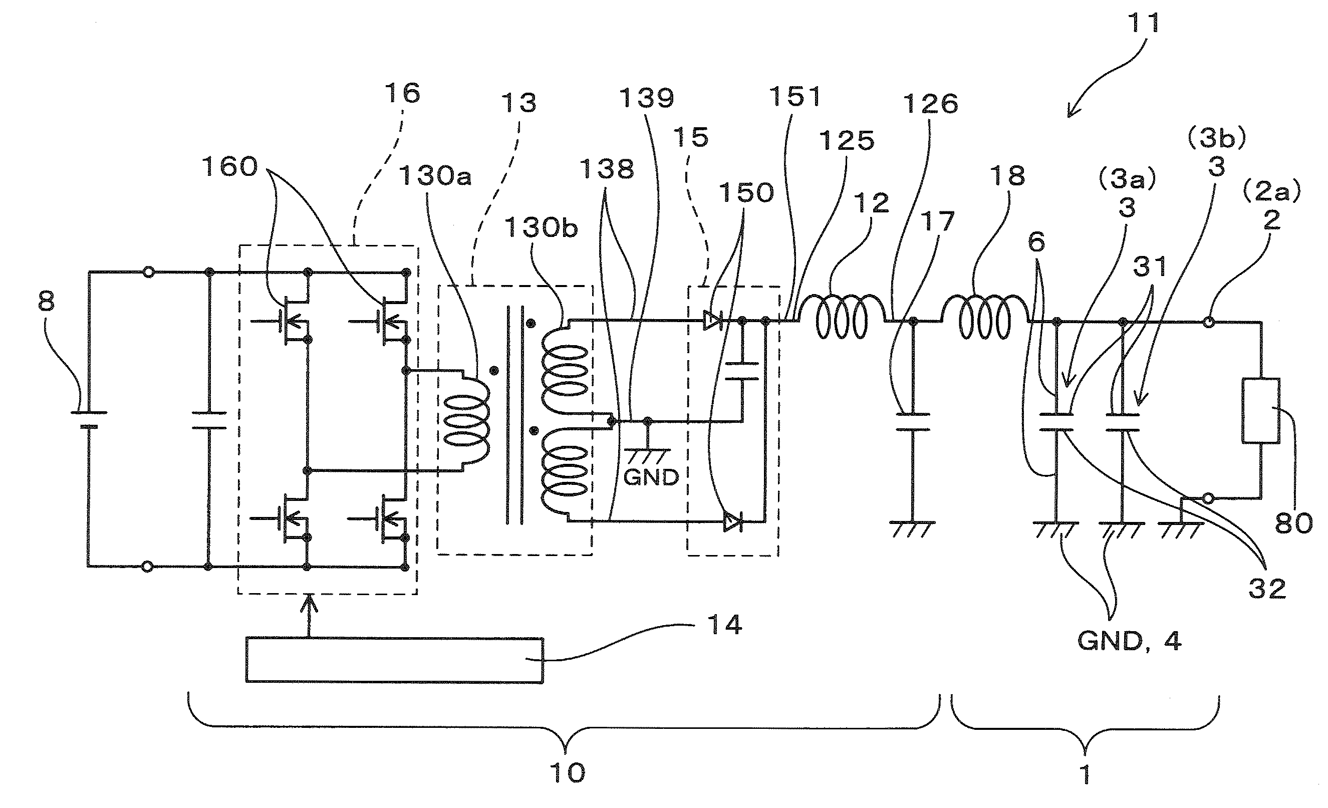
[0043]A description will be given of the noise filter in the electric power conversion device according to a first exemplary embodiment with reference to FIG. 1 to FIG. 9.

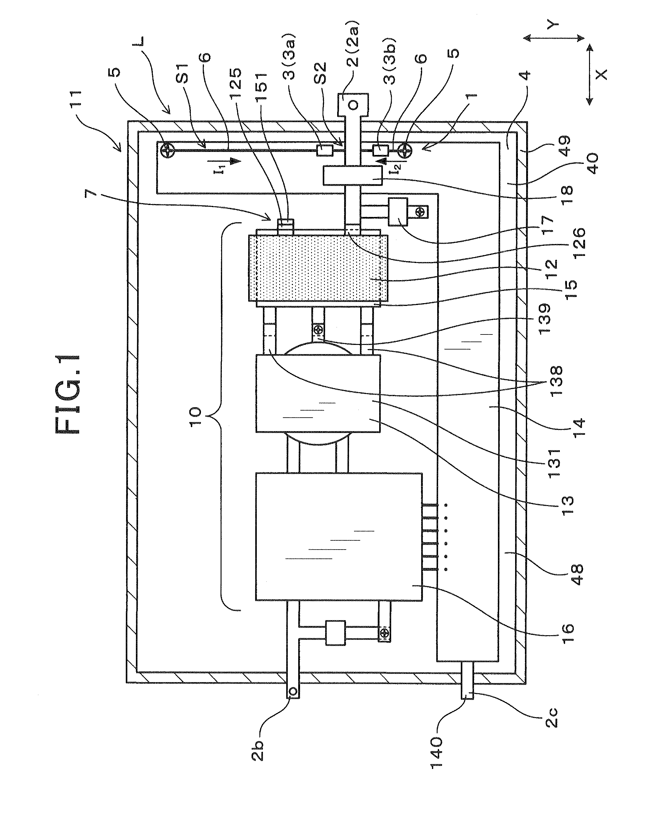
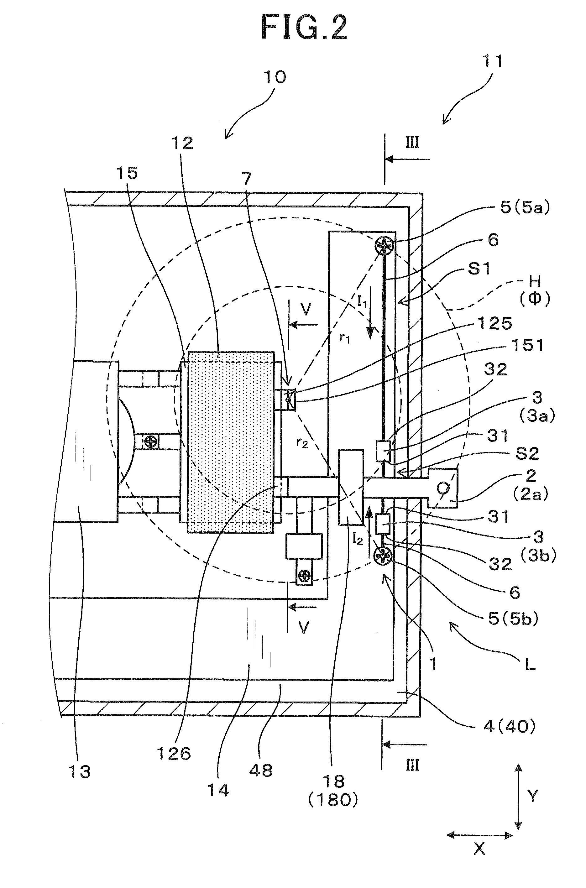
[0044]FIG. 1 is a plan view showing a noise filter 1 according to the first exemplary embodiment assembled to an electric power conversion device 11 equipped with an electric power generation device 10. FIG. 2 is a partial enlarged view showing the noise filter 1 assembled to the electric power conversion device shown in FIG. 1

[0045]As shown in FIG. 1, the noise filter 1 according to the first exemplary embodiment is connected to an external terminal 2 of the electric power conversion circuit 10. The noise filter 1 is comprised of a capacitor assembly 3 composed of a first capacitor 3a and a second capacitor 3b, and a housing casing 4 which is grounded. The first capacitor 3a and the second capacitor 3b are accommodated in the housing casing 4.

[0046]FIG. 3 is a view showing a cross section along the line shown in F...

second exemplary embodiment

[0090]A description will be given of the noise filter according to a second exemplary embodiment with reference to FIG. 10 and FIG. 11.

[0091]FIG. 10 is a partial enlarged view showing the noise filter according to the second exemplary embodiment assembled to the electric power conversion device. FIG. 11 is a view showing a cross section along the XI-XI line shown in FIG. 10.

[0092]As shown in FIG. 10 and FIG. 11, the structure of the current loop L in the noise filter 1 according to the second exemplary embodiment does not contain any conducting wire 6. The first electrode 31 of each of the first capacitor 3a and the second capacitor 3b is electrically connected directly to the external terminal 2. Further, connection members 140 are embedded in the printed circuit substrate 14, which are in contact with the first metal strut 41 and the second metal strut 42, respectively, projected from the bottom surface 48 of the housing casing 4. The second electrode 32 of each of the first capac...

third exemplary embodiment

[0096]A description will be given of the noise filter according to a third exemplary embodiment with reference to FIG. 12.

[0097]FIG. 12 is a plan view showing a pair of the noise filters according to a third exemplary embodiment assembled to the electric power conversion device.

[0098]As shown in FIG. 12, the pair of a first noise filter 1a and a second noise filter 1b is assembled to the electric power conversion device 11. In the structure disclosed in the third exemplary embodiment, the first noise filter 1a is electrically connected to the output terminal 2a in the external terminal 2, and the input terminal 2b of the external terminal 2 is electrically connected to the second noise filter 1b. Further, the input terminal 2b is mounted on the printed circuit substrate 14 and the first capacitor 3c and the second capacitor 3d are fixed to the printed circuit substrate 14. The first electrode 31 of each of the first capacitor 3c and the second capacitor 3d is electrically connected ...


PUM


Abstract

A noise filter is assembled to an electric power conversion device and has a metal housing casing and two capacitors connected to an external terminal of the device through which an electric power conversion circuit is connected to an external device. The two capacitors, the housing casing and the external terminal make a current loop. A magnetic flux of an alternating magnetic field generated in a part of the electric power conversion circuit penetrates in a first area and a second area formed in the current loop. A first induced noise current is induced in the current loop when the magnetic flux of the generated magnetic field penetrates in the first area. A second induced noise current is induced in the current loop when the magnetic flux penetrates in the second area so that the first induced noise current flows in a reverse direction to the second induced noise current.

Description

CROSS-REFERENCE TO RELATED APPLICATION[0001]This application is related to and claims priority from Japanese Patent Application No. 2013-31654 filed on Feb. 21, 2013, the contents of which are hereby incorporated by reference.BACKGROUND OF THE INVENTION[0002]1. Field of the Invention[0003]The present invention relates to noise filters equipped with two capacitors.[0004]2. Description of the Related Art[0005]A conventional technique, for example, Japanese patent laid open publication No. 2012-135175 has disclosed an electric power conversion device for boosting, i.e. increasing a direct current (DC) voltage, and / or decreasing a DC voltage, which is equipped with one or more noise filters. The noise filters decreases and removes a noise current. The noise filter is electrically connected to an input terminal and / or an output terminal of the electric power conversion device. The noise filter removes a noise current which would otherwise be transmitted from an external device into the i...

Claims


Application Information

Patent Timeline
IPC IPC(8): H02M1/12
CPCH02M1/12H02M1/14H02M3/3376
Inventor OHOKA, SHINJIGOTO, SHINYAMISAWA, KATSUTOYOTAKEMOTO, YUUKIYAMAGUCHI, TOUGO
Owner NIPPON SOKEN
Why Eureka
Try Eureka