Torque Shaft and Torque Shaft Drive

a technology of torque shaft and torque shaft, which is applied in the direction of shafts for rotary movement, yielding couplings, couplings, etc., can solve the problems of buckling, kinking, and requiring an excessive amount of initial rotation

Inactive Publication Date: 2014-08-21
AORTX
View PDF16 Cites 22 Cited by
  • Summary
  • Abstract
  • Description
  • Claims
  • Application Information

AI Technical Summary

Problems solved by technology

Typical flexible shafts are susceptible to torque to the extent that rotation of one side of the shaft does not correlate to rotation of the opposite side of the shaft.
Typical shafts are susceptible to buckling, kinking or require an excessive amount of initial rotation at the outset before correlatable torque transmission occurs.

Method used


Image

  • Torque Shaft and Torque Shaft Drive
  • Torque Shaft and Torque Shaft Drive
  • Torque Shaft and Torque Shaft Drive

Examples


Embodiment Construction

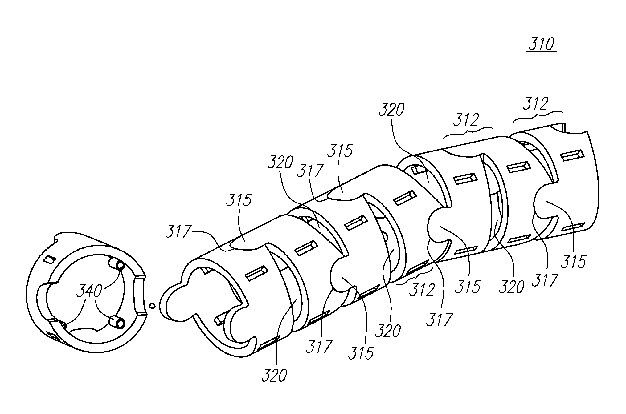
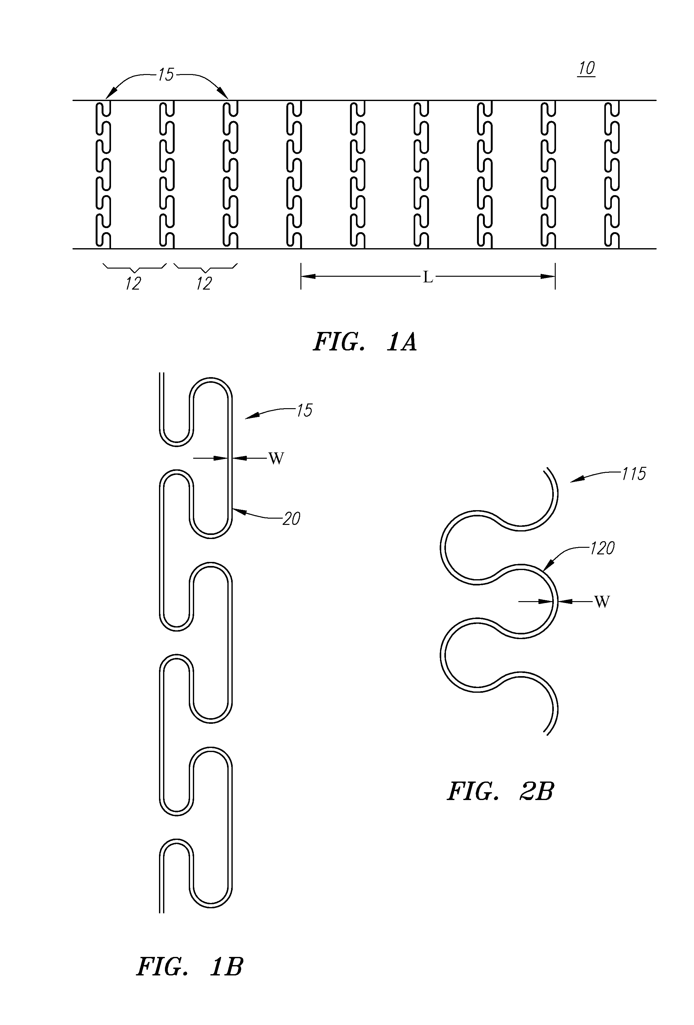
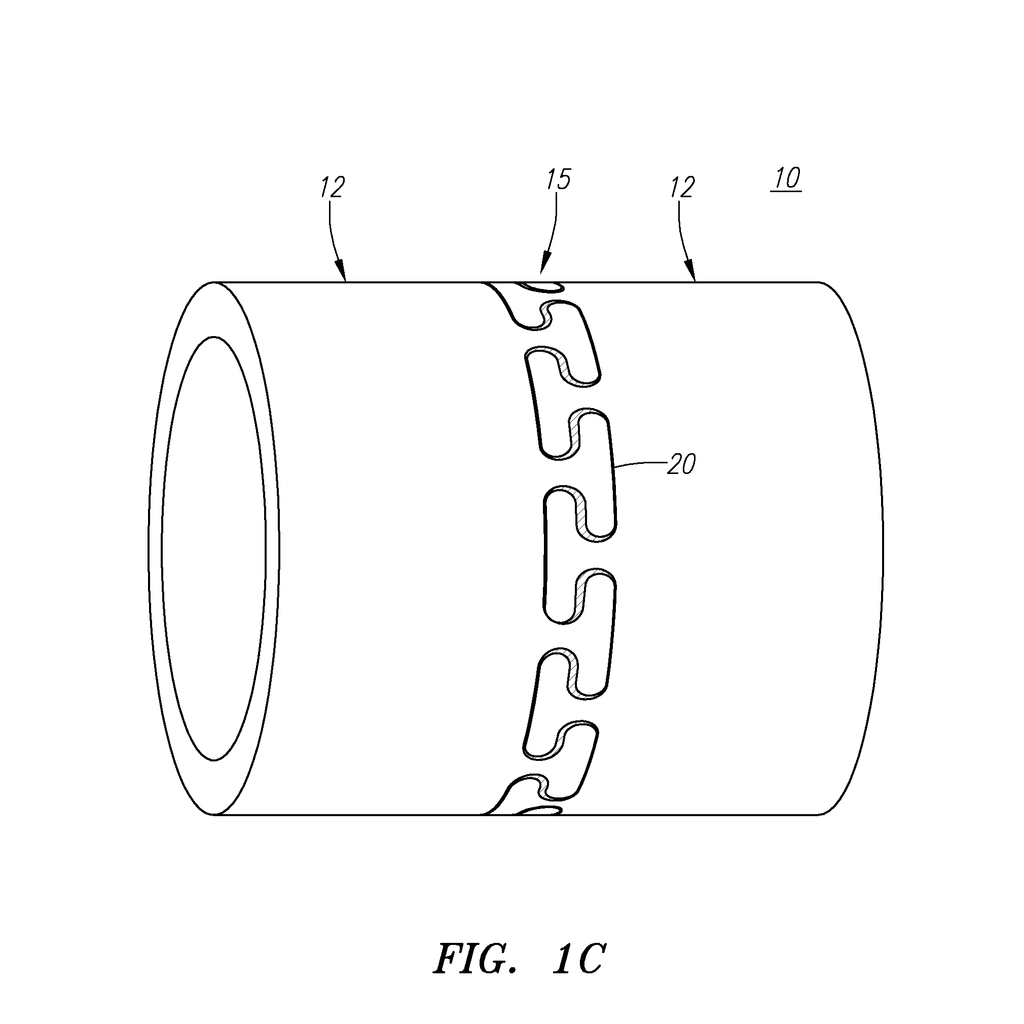
[0013]Torque shafts are described herein. The torque shafts are both flexible and capable of transmitting torque. The torque shafts are useful for procedures that require torque and pushability to drive or deploy a device in any application, such as a medical application constituting use in a patient's body. The flexibility and pushability of the torque shafts enable them to curve along passageways in the body, and the torque transferring capability of the shafts enable them to transmit torque in the body to drive or deploy a device in the body. The torque shafts are particularly useful for the deployment of prosthetic heart valves in a patient's heart, which are described in greater detail in application Ser. No. 11 / 066,126, titled “Prosthetic Heart Valves, Scaffolding Structures, and Systems and Methods for Implantation of Same,” filed on Sep. 15, 2005, the entire specification of which is incorporated by reference. Also described herein is a pull-pull torque drive as an alternati...


PUM


Abstract

Torque shafts and other related systems and methods are described herein. The torque shafts are both flexible and capable of transmitting torque. The torque shafts are useful for procedures that require torque and pushability to drive or deploy a device. The flexibility and pushability of the torque shafts enable them to curve along a tortuous path, and the torque transferring capability of the shafts enable them to transmit torque along the shaft.

Description

CROSS-REFERENCE TO RELATED APPLICATIONS[0001]This application is a continuation of U.S. application Ser. No. 12 / 305,620, filed Dec. 18, 2008, now U.S. Pat. No. 8,376,865, which is a national stage entry under 35 U.S.C. Section 371 of PCT Application Serial No. PCT / US2007 / 071535, filed Jun. 19, 2007, which claims priority to U.S. Provisional Application Ser. No. 60 / 805,334, filed Jun. 20, 2006, all of which are incorporated herein by reference in their entirety.BACKGROUND OF THE INVENTION[0002]Typical flexible shafts are susceptible to torque to the extent that rotation of one side of the shaft does not correlate to rotation of the opposite side of the shaft. For instance, in applications where a shaft is used to transmit torque along a tortuous path to a remote device, it is desirable to maintain a correlation between rotation on one side of the shaft to rotation at the remote device such that the amount of rotation at the remote device can be tracked with certainty. Typical shafts ...

Claims


Application Information

Patent Timeline
Patent Type & Authority Applications(United States)
IPC IPC(8): F16C1/04
CPCF16C1/04
Inventor FORSTER, DAVID C.BECKEY, BRIANWALSH, BRANDON G.HENEVELD, SCOTTROTH, ALEX
Owner AORTX
Why Eureka
Try Eureka