Liquid holding container

Active Publication Date: 2014-08-28
SEIKO EPSON CORP
View PDF5 Cites 0 Cited by
  • Summary
  • Abstract
  • Description
  • Claims
  • Application Information

AI Technical Summary

Benefits of technology

The present invention is about a liquid holding container that prevents air from getting trapped in its filter. The container has two holes, one close to the inlet and one farther away. The liquid flows through the close hole and air flows through the farther hole, eliminating the risk of air getting trapped in the filter. This results in a more efficient and reliable container for holding liquids.

Problems solved by technology

However, such filters trap air (bubbles) inside the ink accommodating container.
When air is trapped in the filter, there is a risk that pressure loss due to the filter will increase and the amount of ink supplied to the printer will be insufficient.

Method used


Image

  • Liquid holding container
  • Liquid holding container
  • Liquid holding container

Examples


first embodiment

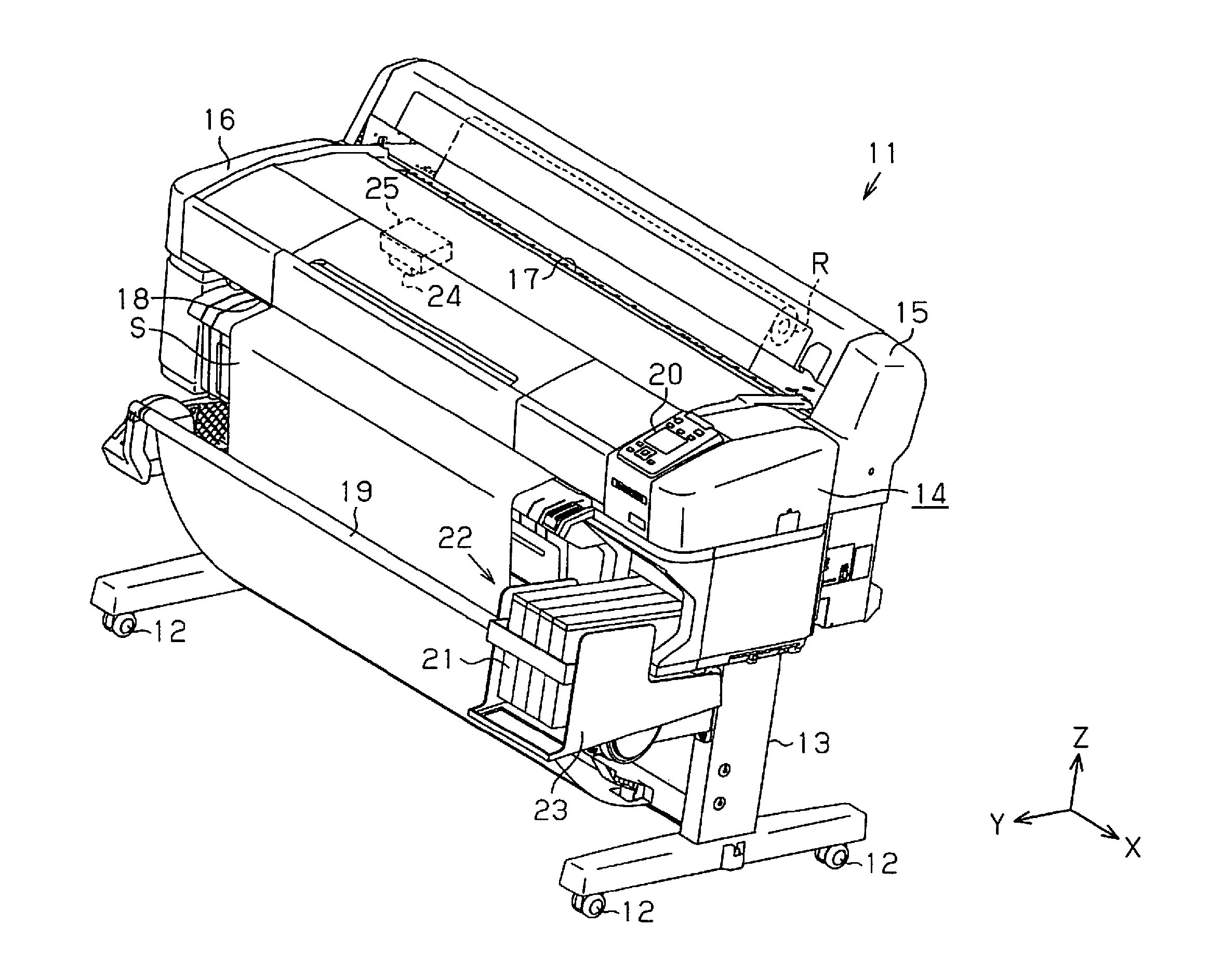
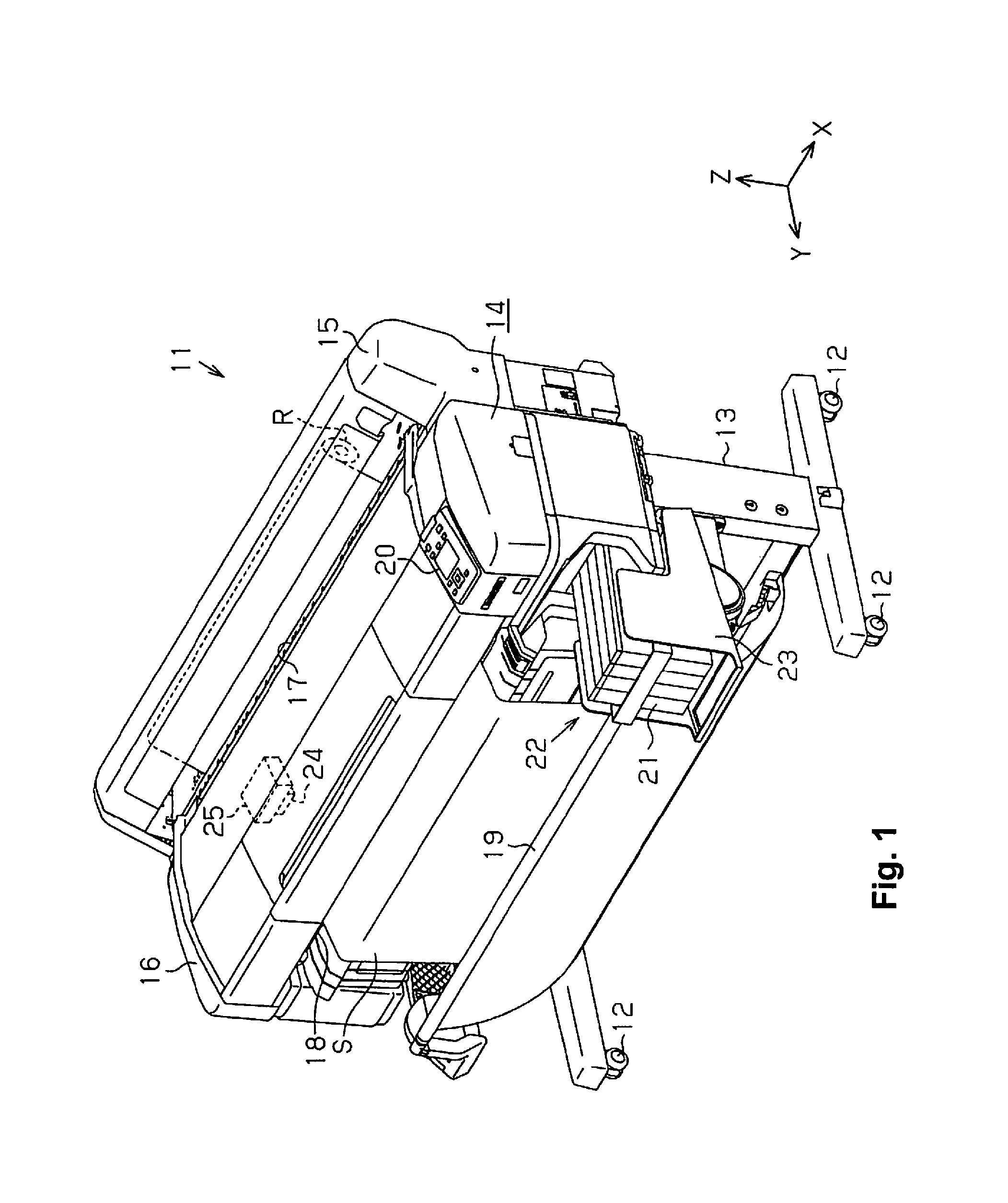
[0070]Below, a first embodiment of a liquid holding container and an ink jet printer (referred to below as a “printer”) which is an example of a liquid consuming apparatus which consumes a liquid which is supplied from the liquid holding container will be described with reference to the diagrams.

[0071]As shown in FIG. 1, a printer 11 of the present embodiment is provided with leg sections 13 where wheels 12 are attached at lower ends, and an apparatus body 14 with a substantially rectangular shape which is assembled on the leg sections 13. Here, the direction along the direction of gravity is an up and down direction Z and the longitudinal direction of the apparatus body 14 which intersects with (is orthogonal to in the present embodiment) the up and down direction Z is a left and right direction X in the present embodiment. In addition, the direction which intersects with (is orthogonal to in the present embodiment) both of the up and down direction Z and the left and right directi...

second embodiment

[0277]Next, a second embodiment which is a liquid holding container will be described with reference to the diagrams. Here, the shape of a cover 210 which covers the case opening section 132 of the accommodating body case 130 in the second embodiment is different to the case of the first embodiment. Then, since the second embodiment is substantially the same as the first embodiment in other respects, overlapping description is omitted by giving the same reference numerals where the configurations are the same.

[0278]As shown FIG. 30 and FIG. 31, at least one reinforcing ridge 211, which extends along an opposing surface 210a which opposes the film 133, is formed at a portion, at the front side which configures the first accommodating body section 37, of the cover 210 which covers the case opening section 132 over the film 133. The reinforcing ridge 211 is formed on an outside surface 210b side which is the opposite side to the facing surface 210a to span in the up and down direction ...


PUM

PropertyMeasurementUnit
Diameteraaaaaaaaaa
Densityaaaaaaaaaa
Flow rateaaaaaaaaaa

Abstract

A liquid holding container includes a liquid accommodating chamber, a flow path, and a filter. The liquid accommodating chamber is configured and arranged to hold liquid. The flow path is communicated with the liquid accommodating chamber via a first through hole and a second through hole. The filter is disposed in the flow path. The first through hole and the second through hole are each communicated with the flow path.

Description

CROSS-REFERENCE TO RELATED APPLICATIONS[0001]This application claims priority to Japanese Patent Application No. 2013-039321 filed on Feb. 28, 2013. The entire disclosure of Japanese Patent Application No. 2013-039321 is hereby incorporated herein by reference.BACKGROUND[0002]1. Technical Field[0003]The present invention relates to a liquid holding container which holds a liquid which is supplied to a liquid consuming apparatus.[0004]2. Related Art[0005]In the prior art, ink jet printers, which perform printing (recording) by ejecting ink (a liquid) from a liquid ejecting head with regard to a target such as paper, are known as a kind of liquid consuming apparatus. Then, an ink accommodating container which supplies ink to such a printer is proposed (for example, Japanese Unexamined Patent Application Publication No. 2007-112151).[0006]A filter for trapping foreign matter is provided in a flow path in the liquid holding container.SUMMARY[0007]However, such filters trap air (bubbles)...

Claims


Application Information

Patent Timeline
IPC IPC(8): B41J2/175
CPCB41J2/17563B41J2/17513
Inventor YAMAGISHI, KENYAMAZAKI, TOSHINOBUIWAMURO, TAKESHINAKAGAWA, SHIGENORITANAKA, RYOICHI
Owner SEIKO EPSON CORP
Why Eureka
Try Eureka