Solenoid valve with a metallic tube bobbin

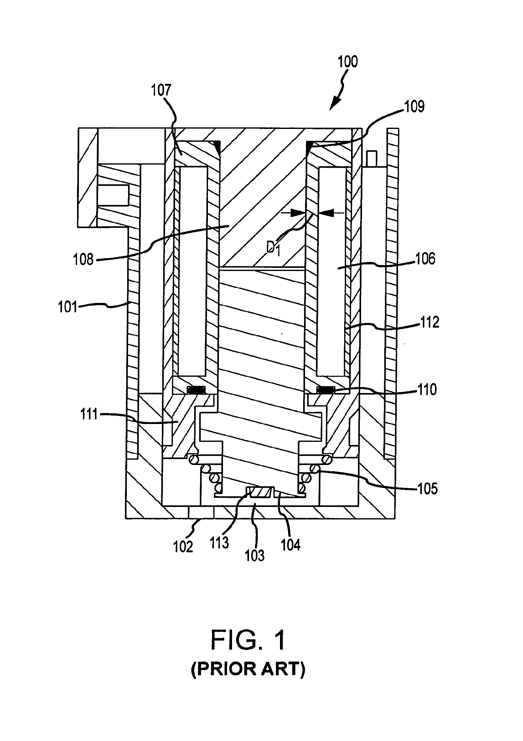
a tube bobbin and solenoid valve technology, applied in the direction of valve operating means/release devices, magnets, magnetic bodies, etc., can solve the problems of electrical short, leakage through the valve, and rendering the valve b>100/b> useless

Inactive Publication Date: 2014-08-28
FAS MEDIC SA
View PDF6 Cites 8 Cited by
  • Summary
  • Abstract
  • Description
  • Claims
  • Application Information

AI Technical Summary

Problems solved by technology

However, the seals 109, 110 are often rubber O-ring seals that can easily degrade resulting in leaking through the valve.
If fluid leaks past the seals 109, 110, there is a chance of fluid reaching the coil 106 resulting in an electrical short and rendering the valve 100 useless.
In addition to the potential for leaks associated with the prior art valve 100, the prior art valve 100 can also suffer from power constraints.
Although the prior art valve 100 may be able to provide adequate performance if the valve's size

Method used


Image

  • Solenoid valve with a metallic tube bobbin
  • Solenoid valve with a metallic tube bobbin
  • Solenoid valve with a metallic tube bobbin

Examples


Embodiment Construction

[0047]FIGS. 2-10 and the following description depict specific examples to teach those skilled in the art how to make and use the best mode of embodiments of a valve. For the purpose of teaching inventive principles, some conventional aspects have been simplified or omitted. Those skilled in the art will appreciate variations from these examples that fall within the scope of the present description. Those skilled in the art will appreciate that the features described below can be combined in various ways to form multiple variations of the solenoid valve. As a result, the embodiments described below are not limited to the specific examples described below, but only by the claims and their equivalents.

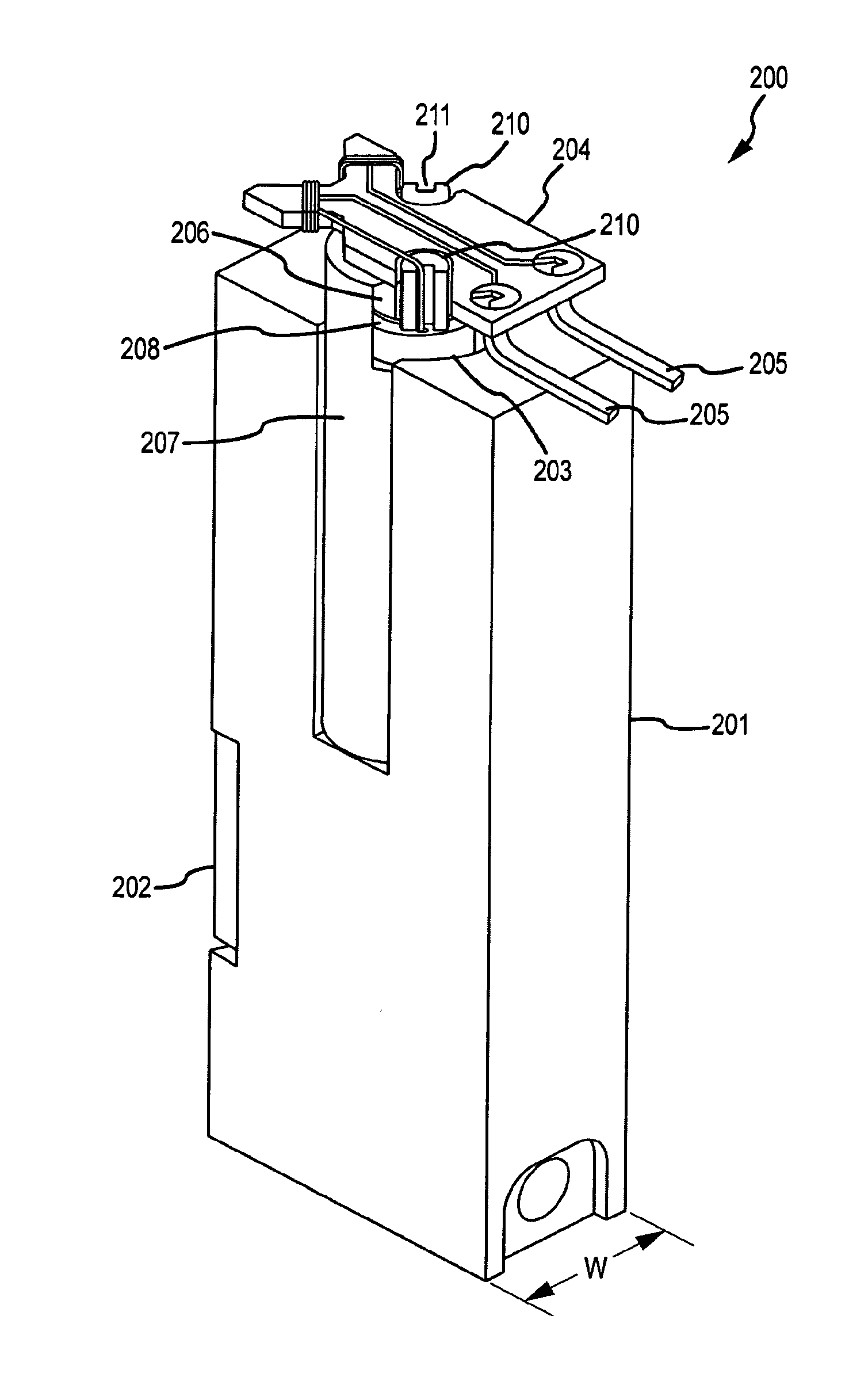
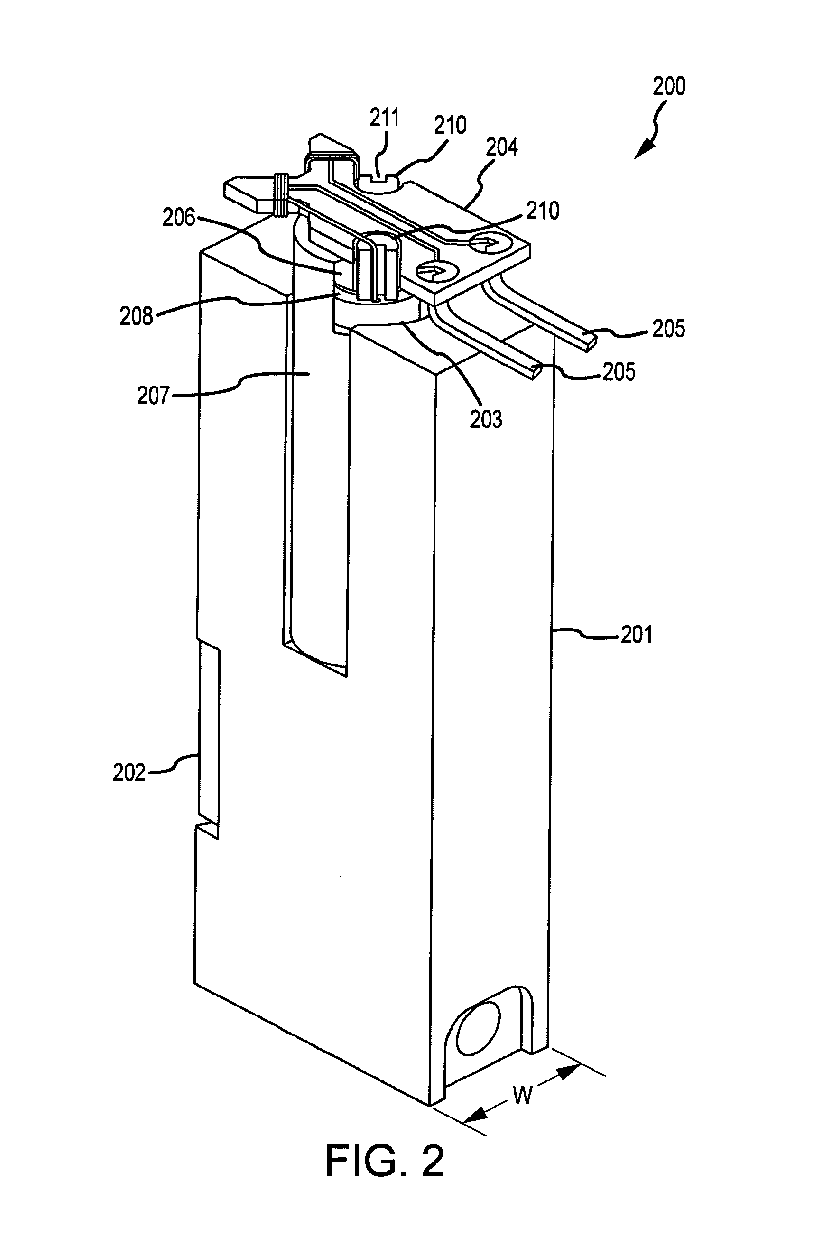
[0048]FIG. 2 shows a solenoid valve 200 according to an embodiment. The solenoid valve 200 comprises a housing 201. The housing 201 includes a port chamber 202 that houses two or more fluid ports (not shown) as well as a valve member that selectively blocks and unblocks the fluid communi...


PUM

PropertyMeasurementUnit
Metallic bondaaaaaaaaaa
Energyaaaaaaaaaa

Abstract

A solenoid valve (200) is provided. The solenoid valve (200) comprises a fixed core (206) and a movable armature (420). The solenoid valve (200) further comprises a metallic tube bobbin (308) surrounding at least a portion of the fixed core (206) and/or the movable armature (420). A wire coil (203) is wrapped around the metallic tube bobbin (308).

Description

TECHNICAL FIELD[0001]The embodiments described below relate to, solenoid valves, and more particularly, to a solenoid valve with a metallic tube bobbin.BACKGROUND OF THE INVENTION[0002]Fluid control valves are used in a wide variety of applications to control the flow of a fluid. The fluid being controlled may comprise a gas, a liquid, or a combination thereof. In some situations, the fluid may also include suspended particulates. While fluid control valves vary widely in the specific configuration used to open and close a fluid communication path through the valve, one specific type of valve actuation is performed using a solenoid. In solenoid-actuated valves, the solenoid comprises an electric current that passes through an electromagnetic coil, with the coil typically formed around a magnetic core. The coil generally comprises a wire that is wrapped around a plastic bobbin numerous times resulting in a plurality of so-called turns. The energized solenoid generates a magnetic fiel...

Claims


Application Information

Patent Timeline
IPC IPC(8): F16K31/06
CPCF16K31/0675F16K31/0668H01F5/04H01F7/127H01F27/027H01F2007/062Y10T29/49412
Inventor ALVAREZ, RAPHAELSIRDEY, PIERRE
Owner FAS MEDIC SA
Why Eureka
Try Eureka