Integrated radio frequency connector

a radio frequency connector and integrated technology, applied in the direction of one-pole connection, coupling device connection, coupling device details, etc., can solve the problems of increasing the overall cost of conductive wires, increasing the complexity and difficulty of assembling, and increasing the assembling time, so as to improve the effect of receiving and transmitting data signals, saving material costs of conductive wires, and quick assembling

Active Publication Date: 2014-08-28
GRAND TEK TECH
View PDF9 Cites 0 Cited by
  • Summary
  • Abstract
  • Description
  • Claims
  • Application Information

AI Technical Summary

Benefits of technology

[0007]1. The built-in radio frequency part and the connecting element are electrically coupled to the main board simply by a conductive wire, so that the material cost of the conductive wire can be saved.
[0008]2. The modular design of installing the connecting element to the built-in radio frequency part provides a quick assembling method.
[0009]3. The grounding element is electrically coupled to the built-in radio frequency part and the main board to improve the effects of receiving and transmitting data signals by the built-in radio frequency part.
[0010]4. The fixing pin of the connecting element is passed and fixed into the fixing hole of the built-in radio frequency part to secure the connecting element and fix with the built-in radio frequency part to achieve the effect of preventing the connecting element from falling apart from the built-in radio frequency part.

Problems solved by technology

However, the conventional built-in radio frequency unit and the external radio frequency connector are installed on a main board of the electronic product separately, so that the built-in radio frequency unit and the external radio frequency connector must be electrically coupled to the main board through conductive wires, and thus the conductive wires increase the overall cost.
In addition, it is necessary to install the built-in radio frequency unit and the external radio frequency connector onto the main board individually, and the assembling procedure becomes more complicated and difficult, and the assembling time becomes longer.

Method used


Image

  • Integrated radio frequency connector
  • Integrated radio frequency connector
  • Integrated radio frequency connector

Examples


Embodiment Construction

[0016]The technical contents of the present invention will become apparent with the detailed description of preferred embodiments accompanied with the illustration of related drawings as follows. It is intended that the embodiments and figures disclosed herein are to be considered illustrative rather than restrictive.

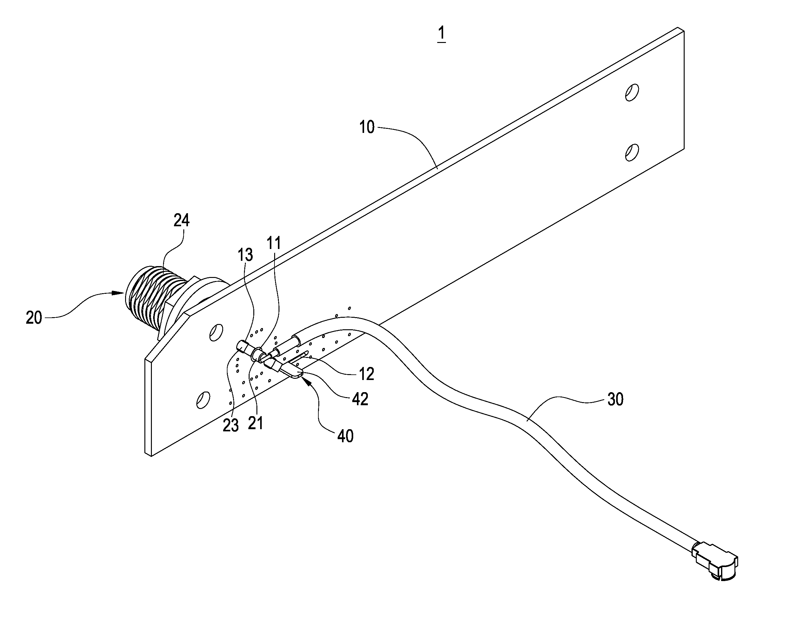
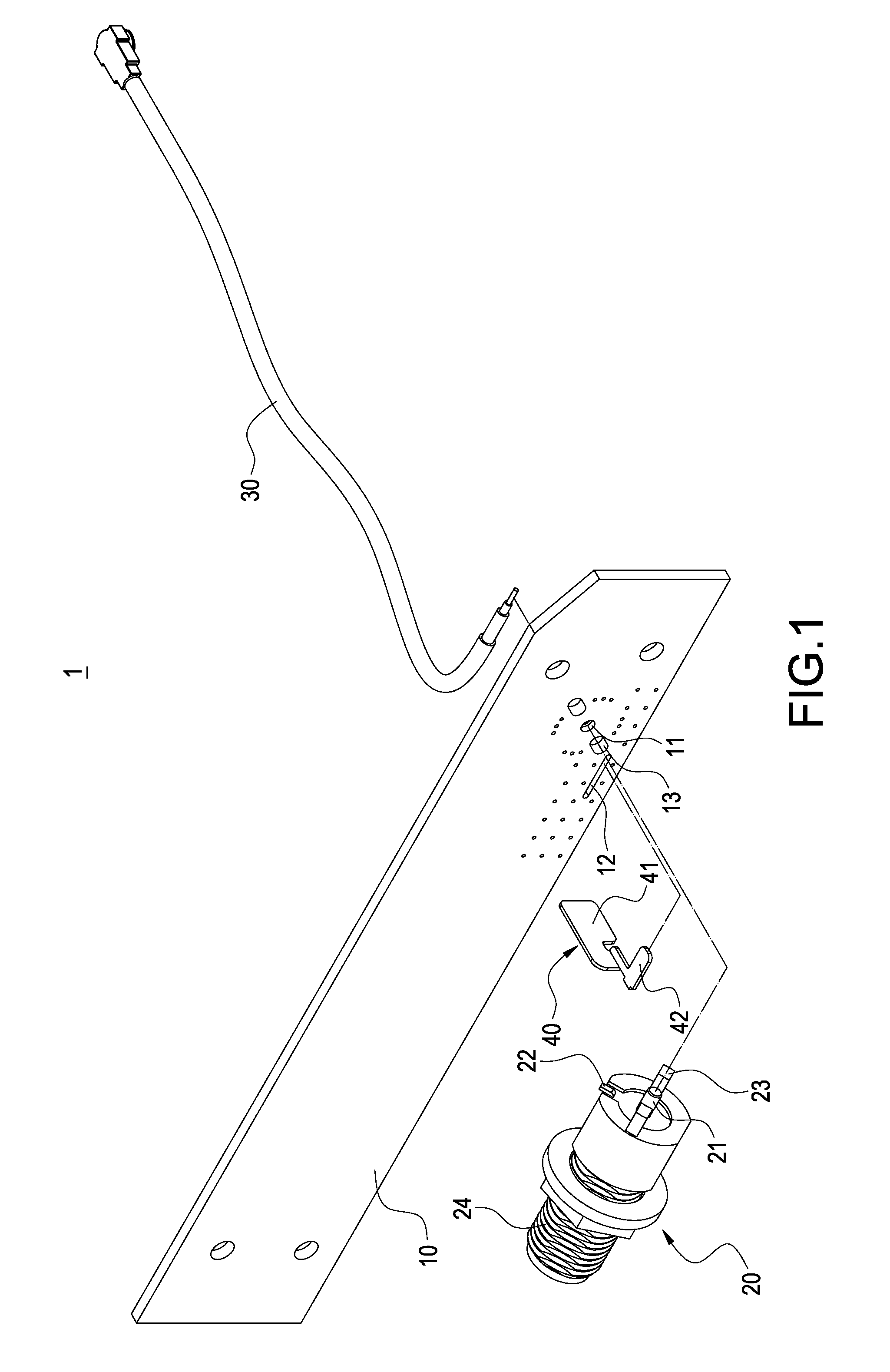
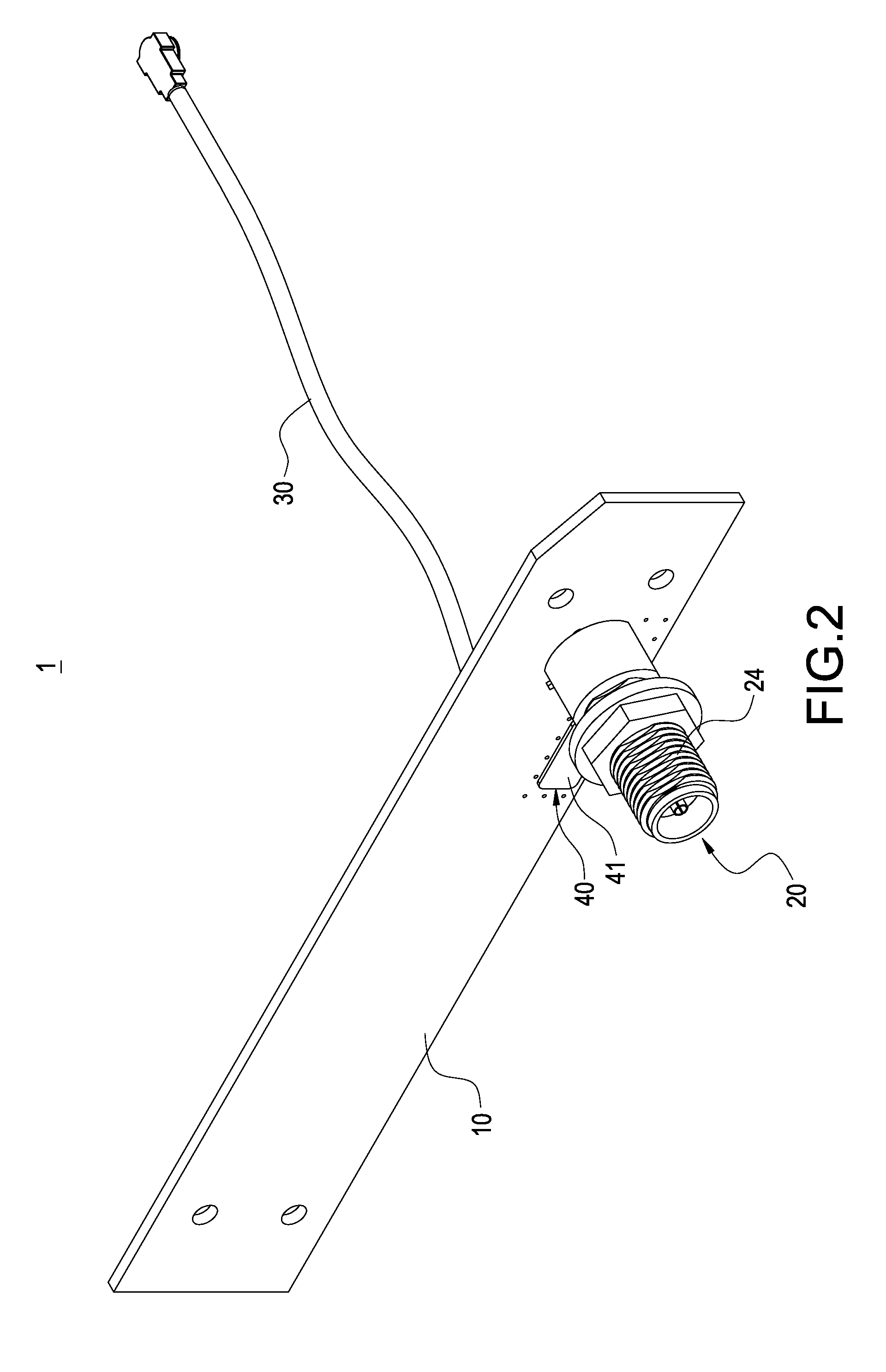
[0017]With reference to FIGS. 1 to 3 for an exploded view, a perspective view and a schematic view of the present invention, respectively, the present invention provides an integrated radio frequency connector 1 installed to a main board 9 (shown in FIG. 4 or 5) and comprising a built-in radio frequency part 10, a connecting element 20 and a conductive wire 30.

[0018]The built-in radio frequency part 10 has a through hole 11, a penetrating hole 12 and a fixing hole 13, and further includes a circuit board and a radio frequency circuit formed on a circuit board.

[0019]The connecting element 20 is a coaxial connector installed and electrically coupled to the built-in radio ...


PUM


Abstract

An integrated radio frequency connector installed in a main board includes a built-in radio frequency part, a connecting element and conductive wire. The connecting element is installed and electrically coupled to the built-in radio frequency part, and the connecting element has a conductive terminal protruded from the built-in radio frequency part, and an end of the conductive wire is electrically coupled to the conductive terminal, and the other end of the conductive wire is electrically coupled to the main board to achieve a modular design, so as to facilitate the assembling procedure.

Description

FIELD OF THE INVENTION[0001]The present invention relates to a connector, and more particularly to an integrated radio frequency connector.BACKGROUND OF THE INVENTION[0002]In general, an electronic communication product comes with a built-in radio frequency unit and an external radio frequency connector, so that the electronic product is capable of receiving or transmitting signals through the built-in radio frequency unit and electrically connecting an external radio frequency unit to the external radio frequency connector to receive or transmit the signals through the external radio frequency unit.[0003]However, the conventional built-in radio frequency unit and the external radio frequency connector are installed on a main board of the electronic product separately, so that the built-in radio frequency unit and the external radio frequency connector must be electrically coupled to the main board through conductive wires, and thus the conductive wires increase the overall cost. In...

Claims


Application Information

Patent Timeline
Patent Type & Authority Applications(United States)
IPC IPC(8): H01R13/66H01Q1/50
CPCH01R13/665H01Q1/50H01R13/6658H01R24/50H01R2101/00H01R2201/02H01R13/719
Inventor YU, HAN-HSUAN
Owner GRAND TEK TECH
Why Eureka
Try Eureka