
Image forming apparatus

a technology of forming apparatus and moving path, which is applied in the direction of electrographic process apparatus, instruments, optics, etc., can solve the problems of increasing material costs, increasing the number of parts, and bulky apparatus, and achieve the effect of shortening the moving path and reducing the whole size of the apparatus

Active Publication Date: 2010-11-09
HEWLETT PACKARD DEV CO LP
View PDF20 Cites 0 Cited by
  • Summary
  • Abstract
  • Description
  • Claims
  • Application Information

AI Technical Summary

Benefits of technology

The present invention provides an image forming apparatus that reduces the size of the apparatus by shortening the paper moving path and saves material costs by omitting a feeding roller. The apparatus includes a laser scanning unit, a photoconductive medium, a developing roller, a transferring roller, a pickup roller, a paper edge sensor, and a transfer nip. The pickup roller picks up paper from a paper supplying part and the paper is transferred directly to the photoconductive medium using the developing roller and transferring roller. The rotational speed of the pickup roller is faster than that of the photoconductive medium. The apparatus allows for vertical transfer of paper and includes a paper edge sensor for sensing the top end of the paper. The technical effects of the invention are reduced size and cost savings.

Problems solved by technology

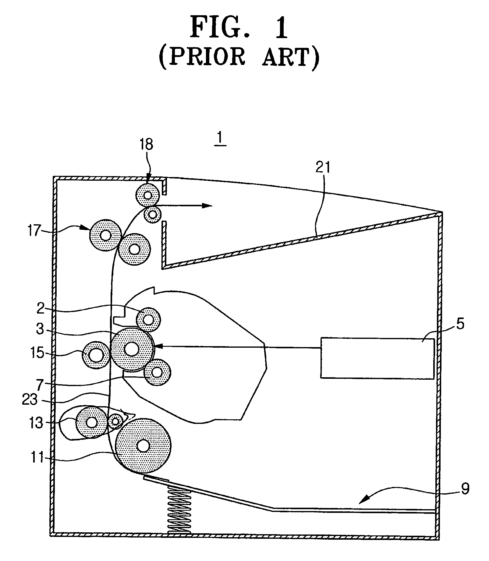
However, since the conventional image forming apparatus has to include a dedicated feeding roller 13 for moving the paper picked up by the pickup roller 11 to the photoconductive medium 3, a paper path 23 is generally long, and accordingly, the whole apparatus becomes bulky.
Also, providing the dedicated feeding roller 13, the number of parts increases, thereby increasing material costs.

Method used


Image

  • Image forming apparatus
  • Image forming apparatus
  • Image forming apparatus

Examples


Embodiment Construction

[0029]Hereinafter, exemplary embodiments of the present invention are described in detail with reference to the accompanying drawing figures.

[0030]The matters defined in the description, such as a detailed construction and elements thereof, are provided to assist in a comprehensive understanding of the invention. Thus, it is apparent that various changes and modifications to the examples described herein may be made without departing from the scope of the present invention. Also, well-known functions or constructions are omitted to provide a clear and concise description.

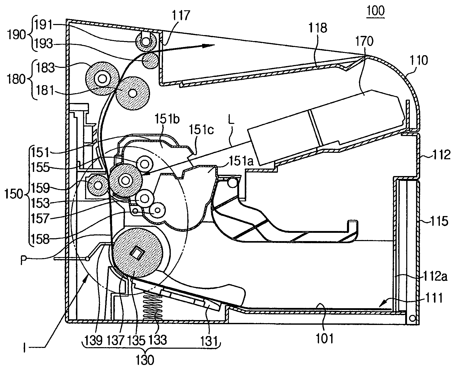
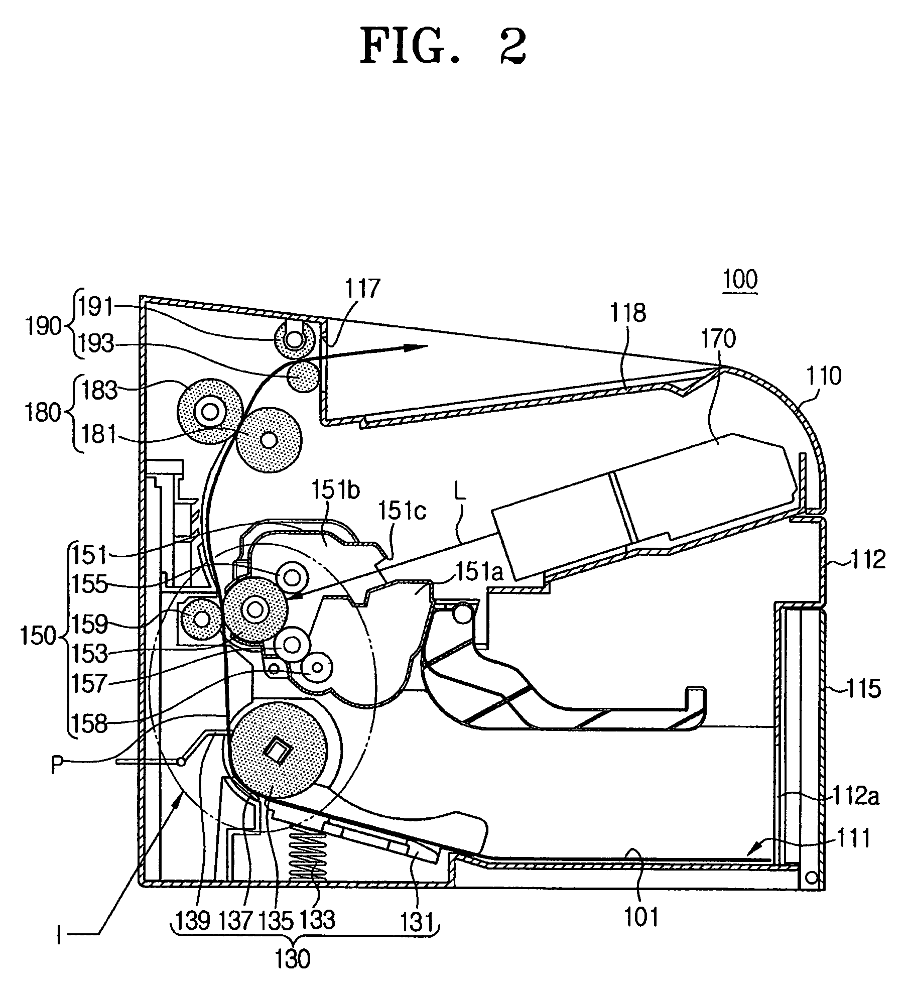
[0031]FIG. 2 is a sectional view schematically showing the whole structure of an image forming apparatus according to an embodiment of the present invention.

[0032]Referring to FIG. 2, an image forming apparatus 100 includes a main body 110, a paper supplying unit 130, a developing unit 150, a laser scanning unit 170, a fusing unit 180 and a paper discharging unit 190.

[0033]The main body 110 has a cover 112 constitut...


PUM


Abstract

An image forming apparatus includes a laser scanning unit that irradiates a light. A photoconductive medium forms thereon an electrostatic latent image using the light from the laser scanning unit. A developing roller transfers a developer onto the electrostatic latent image formed on the photoconductive medium to develop the electrostatic latent image. A transferring roller forms a transfer nip in tight contact with the photoconductive medium and transfers the developer attached on the photoconductive medium onto a paper passing through the transfer nip. A paper supplying part stacks the paper thereon. A pickup roller picks up the paper stacked on the paper supplying part. A paper edge sensor senses a top edge of the paper picked up by the pickup roller. The paper picked up by the pickup roller is directly supplied toward the transfer nip. A paper moving path is reduced, thereby minimizing the whole size of the image forming apparatus. Also, the number of parts is reduced, thereby decreasing material costs.

Description

CROSS-REFERENCE TO RELATED APPLICATIONS[0001]This application claims the benefit under 35 U.S.C. §119(a) of Korean Patent Application No. 2004-78304, filed Oct. 1, 2004, in the Korean Intellectual Property Office, the entire disclosure of which is hereby incorporated by reference.BACKGROUND OF THE INVENTION[0002]1. Field of the Invention[0003]The present invention relates to an image forming apparatus. More particularly, the present invention relates to an image forming apparatus enabling a printing paper picked up by a pickup roller to be directly transferred from a paper supplying part to a photoconductive medium.[0004]2. Description of the Related Art[0005]Generally, an electrophotographic image forming apparatus, such as laser beam printer, produces an electrostatic latent image on a photoconductive medium, for example, a photoconductive belt. The electrostatic latent image is developed by developers of certain colors and the developed image is transferred onto a paper, thereby ...

Claims


Application Information

Patent Timeline
Patent Type & Authority Patents(United States)
IPC IPC(8): G03G15/00
CPCG03G15/6558G03G15/16G03G15/6511G03G15/657G03G15/751
Inventor LIM, KWANG-TAEKCHO, WON-MO
Owner HEWLETT PACKARD DEV CO LP
Learn More