
Method and system for dynamic allocation of resources in a cellular network

a technology of dynamic allocation and cellular network, applied in the direction of criteria allocation, digital transmission, transmission path sub-channel allocation, etc., can solve the problems of limiting the x2-based icic solution to the area, if not impossible, and the requirement of having one vendor's equipment too restrictive,

Active Publication Date: 2014-08-28
CISCO TECH INC
View PDF2 Cites 59 Cited by
  • Summary
  • Abstract
  • Description
  • Claims
  • Application Information

AI Technical Summary

Benefits of technology

The present patent is about a method and system for dynamically allocating air interface resources in a cellular network. The method involves determining classification rules for mobile devices based on factors like location and signal strength, and providing information to base stations about which parts of air interface resource blocks will be used by each base station. The base stations can then communicate with each other to coordinate which parts of the resources will be used. The system can also include a central management entity that determines the classification rules and provides information to the base stations. The technical effect of this patent is to enable dynamic allocation of air interface resources in a cellular network, which can improve network performance and efficiency.

Problems solved by technology

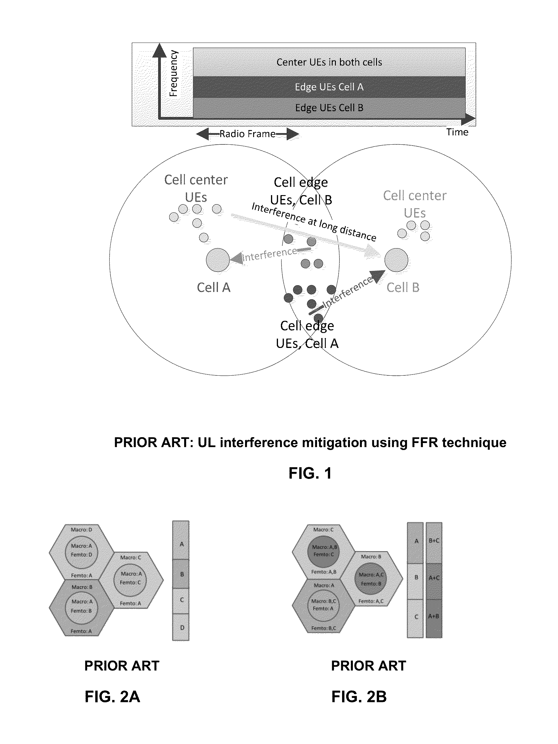
This essentially limits the X2-based ICIC solution to areas where the base stations originate from a single vendor.
While in existing macro deployments this constrain might still be achieved, for modern multi-RAT networks (LTE overlay over UMTS network) and HetNet networks, such a requirement of having one vendor's equipment is too restrictive, if not impossible.
However, heterogeneous networks pose new ICIC challenges.

Method used


Image

  • Method and system for dynamic allocation of resources in a cellular network
  • Method and system for dynamic allocation of resources in a cellular network
  • Method and system for dynamic allocation of resources in a cellular network

Examples


Embodiment Construction

[0060]In this disclosure, the term “comprising” is intended to have an open-ended meaning so that when a first element is stated as comprising a second element, the first element may also include one or more other elements that are not necessarily identified or described herein, or recited in the claims.

[0061]In the following description, for the purposes of explanation, numerous specific details are set forth in order to provide a better understanding of the present disclosure by way of examples. It should be apparent, however, that the present disclosure may be practiced without these specific details.

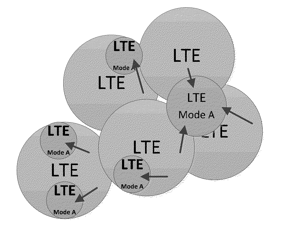
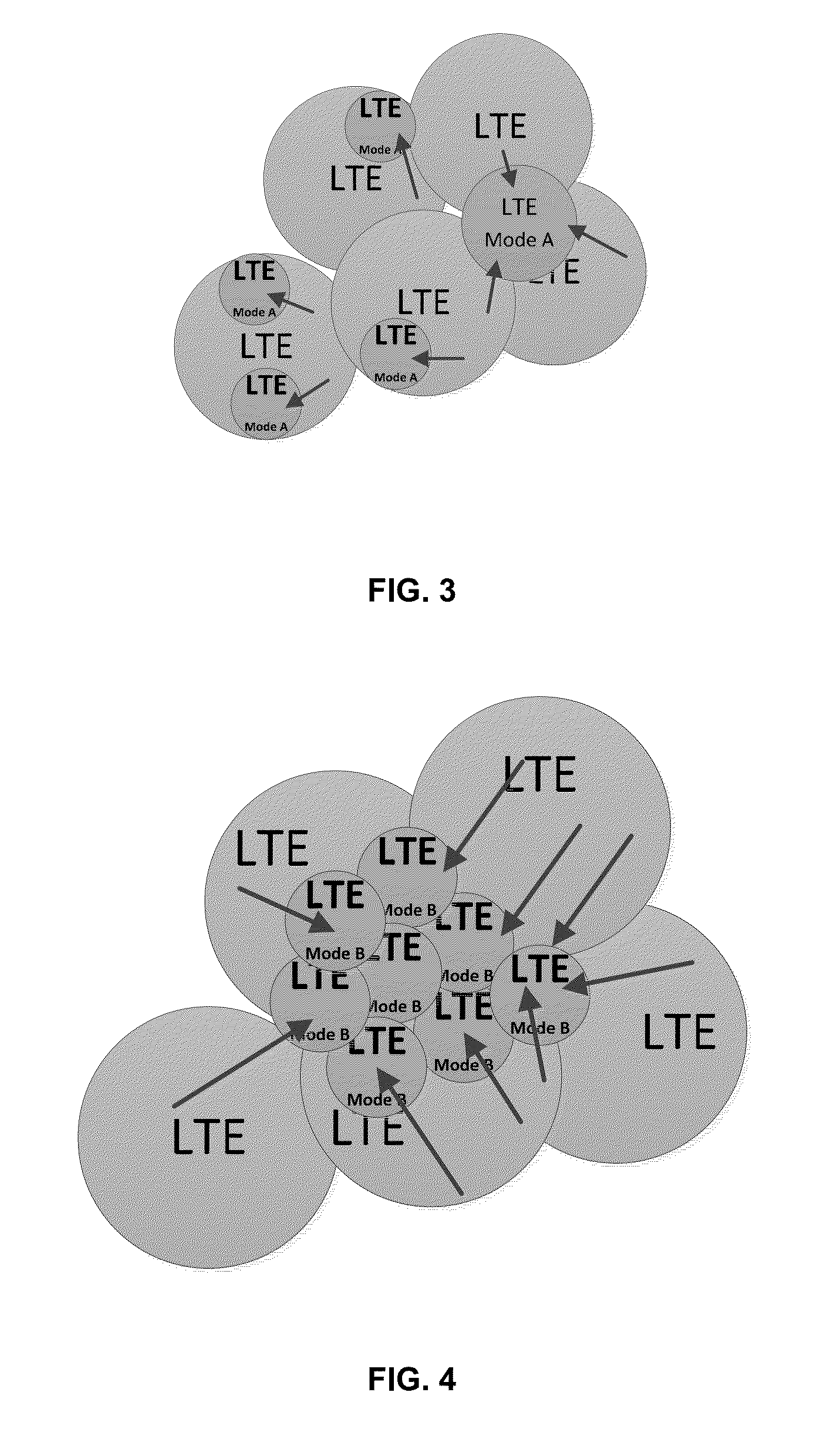
[0062]Let us consider a particular example of deploying eNBs in a HetNet, which comprises small cells (i.e. metro cells), wherein the eNBs are configured to operate in one of the following two modes:

TABLE 1ModeDefinitionMode A (Prior art)The MLB dSON function is disabled by thecSON over Itf-N. The cSON application directlymanages the eNB parameters over Itf-N as specifiedin 3GPP TS 2...


PUM


Abstract

One example method is provided for dynamic allocation of air interface resources in a cellular network comprising at least three wireless cells located within a geographical proximity of each other, the method comprising determining, by a central managing entity, one or more classification rules for classifying each of said plurality of mobile devices according to the one or more classification rules; providing, by the central management entity, to a group of base stations associated with the at least three cells, information that comprises: information that relates to the determined one or more classification rules; information that relates to semi-static allocation of blocks of air interface resources adapted for use by one or more specific members of the group of base stations.

Description

CROSS-REFERENCE TO RELATED APPLICATIONS[0001]This application is based on and claims the benefit of priority under 35 U.S.C. §119 from Israeli Patent Application No. 224926 filed in the Israel Patent Office on Feb. 26, 2013, entitled “METHOD AND SYSTEM FOR DYNAMIC ALLOCATION OF RESOURCES IN A CELLULAR NETWORK,” the contents of which are hereby incorporated by reference in their entirety.TECHNICAL FIELD[0002]The disclosure relates to a system and a method for allocating resources in wireless networks, and in particularly to allocating resources and mitigating interference in cellular mobile communication systems.BACKGROUND[0003]The 3GPP Long Term Evolution (“LTE”) Specifications define two types of interference mitigation techniques: The first one being interference mitigation by interference reduction, and the second one is interference mitigation by inter cell interference coordination (ICIC). The 3GPP standard handles the two types of interference minimization differently. The fir...

Claims


Application Information

Patent Timeline
IPC IPC(8): H04L5/00
CPCH04L5/0096H04L5/0094H04W28/16H04W72/04H04L5/0035H04L5/0073H04L5/0053H04W72/541H04W88/02H04W88/08H04W72/0453
Inventor YANOVER, VLADIMIRNUSS, ZIV
Owner CISCO TECH INC
Learn More