

Detection circuit, driving method, probe, and subject information acquiring apparatus
a technology of subject information acquisition and detection circuit, which is applied in the direction of instruments, specific gravity measurement, applications, etc., can solve the problems of increasing the temperature of the probe, the new problem of heat generation in the preamplifier or the current-voltage conversion circuit, and the characteristic of the probe may be changed
- Summary
- Abstract
- Description
- Claims
- Application Information
AI Technical Summary
Benefits of technology
Problems solved by technology
Method used
Image

Examples
first exemplary embodiment
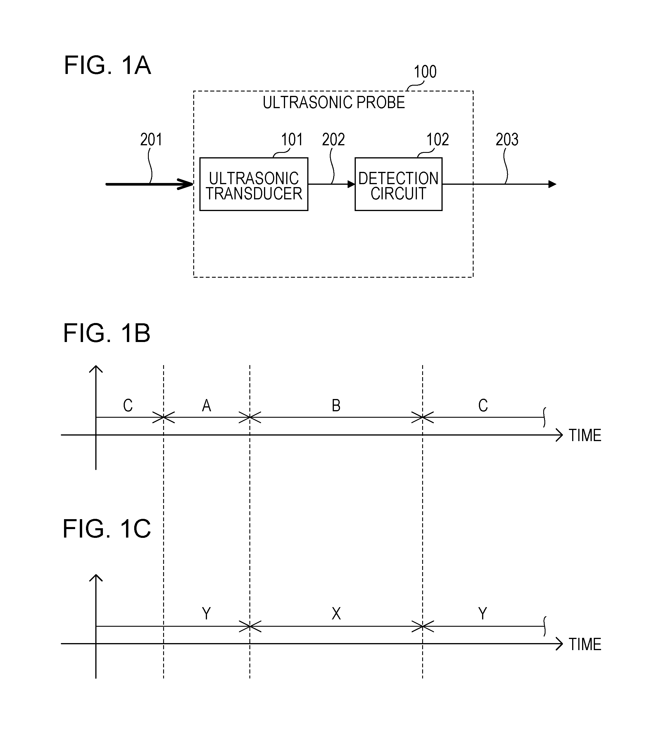
[0024]FIG. 1A is an explanatory diagram for describing a configuration of the ultrasonic probe according to the present exemplary embodiment. In FIG. 1A, an ultrasonic probe 100, an ultrasonic transducer 101, a detection circuit 102, a reception ultrasonic wave 201, a detection signal 202, and a detection output signal 203 are illustrated. When the transducer 101 receives the ultrasonic wave 201, the detection signal 202 is output from the transducer 101 and input to the detection circuit 102. Since the detection signal 202 is an extremely faint signal, the detection signal 202 is converted into a signal to be output to an external part by the detection circuit 102 and is output as the detection output signal 203.
[0025]FIGS. 1B and 1C are explanatory diagrams for describing operations conducted by the detection circuit 102 and the ultrasonic probe 100 according to the present exemplary embodiment. FIG. 1B represents a period for each operation mode of the ultrasonic probe 100. FIG. ...
second exemplary embodiment
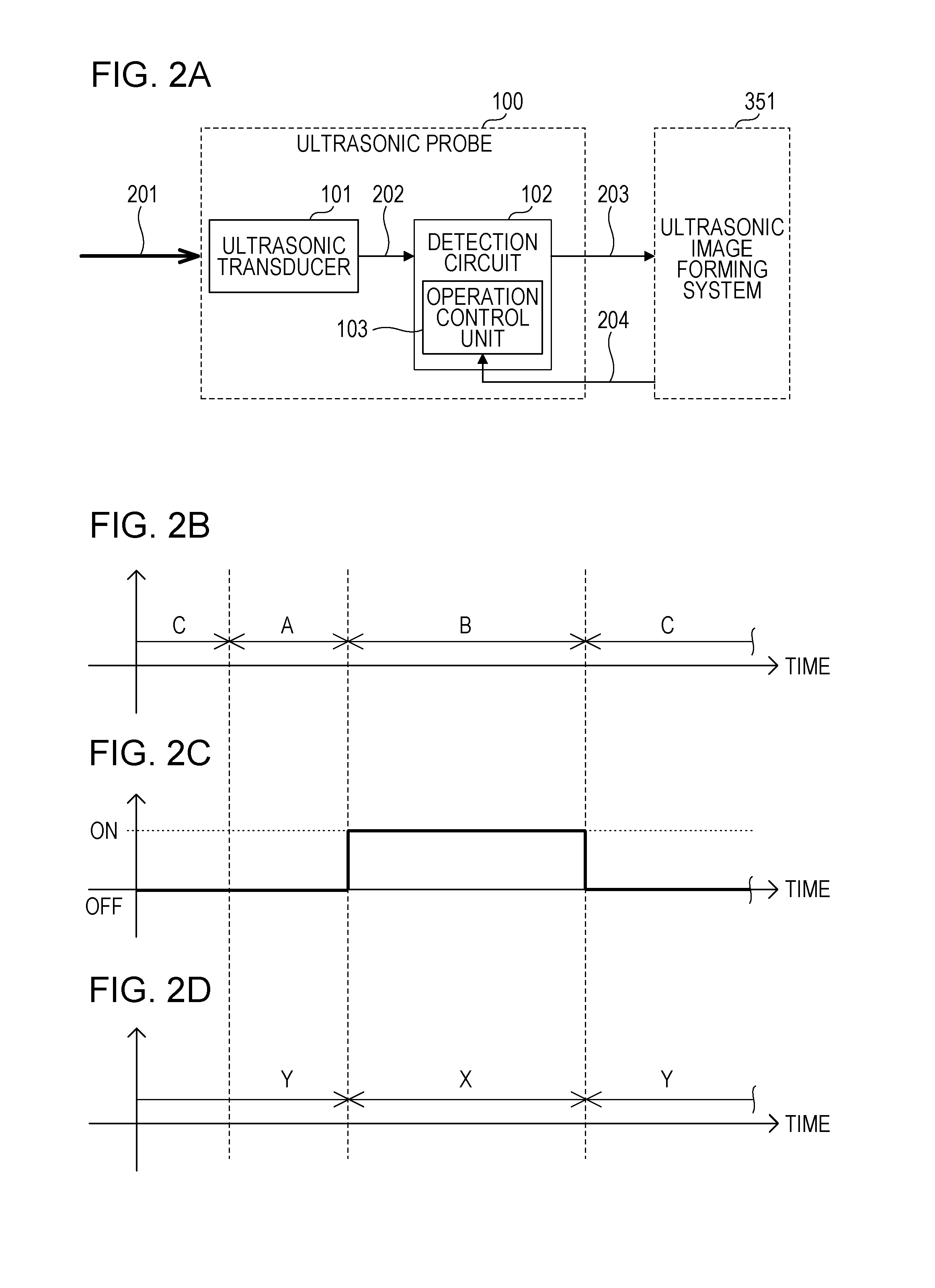
[0039]Next, a description will be given of a second exemplary embodiment by using FIG. 2. A difference of the second exemplary embodiment from the first exemplary embodiment resides in that the detection circuit includes the detection circuit operation control unit 103. The other configuration is the same as the first exemplary embodiment. According to the present exemplary embodiment, the detection circuit operation control unit 103 causes the detection circuit to operate or not to operate on the basis of a reception period signal. FIG. 2A is an explanatory diagram for describing the configurations of the detection circuit 102 and the ultrasonic probe 100 according to the present exemplary embodiment. In FIG. 2A, the detection circuit operation control unit 103, and an operation signal 204. FIGS. 2B, 2C, and 2D are explanatory diagrams for describing operations conducted by the detection circuit 102 and the ultrasonic probe 100. FIG. 2B represents a period for each operation mode o...
third exemplary embodiment
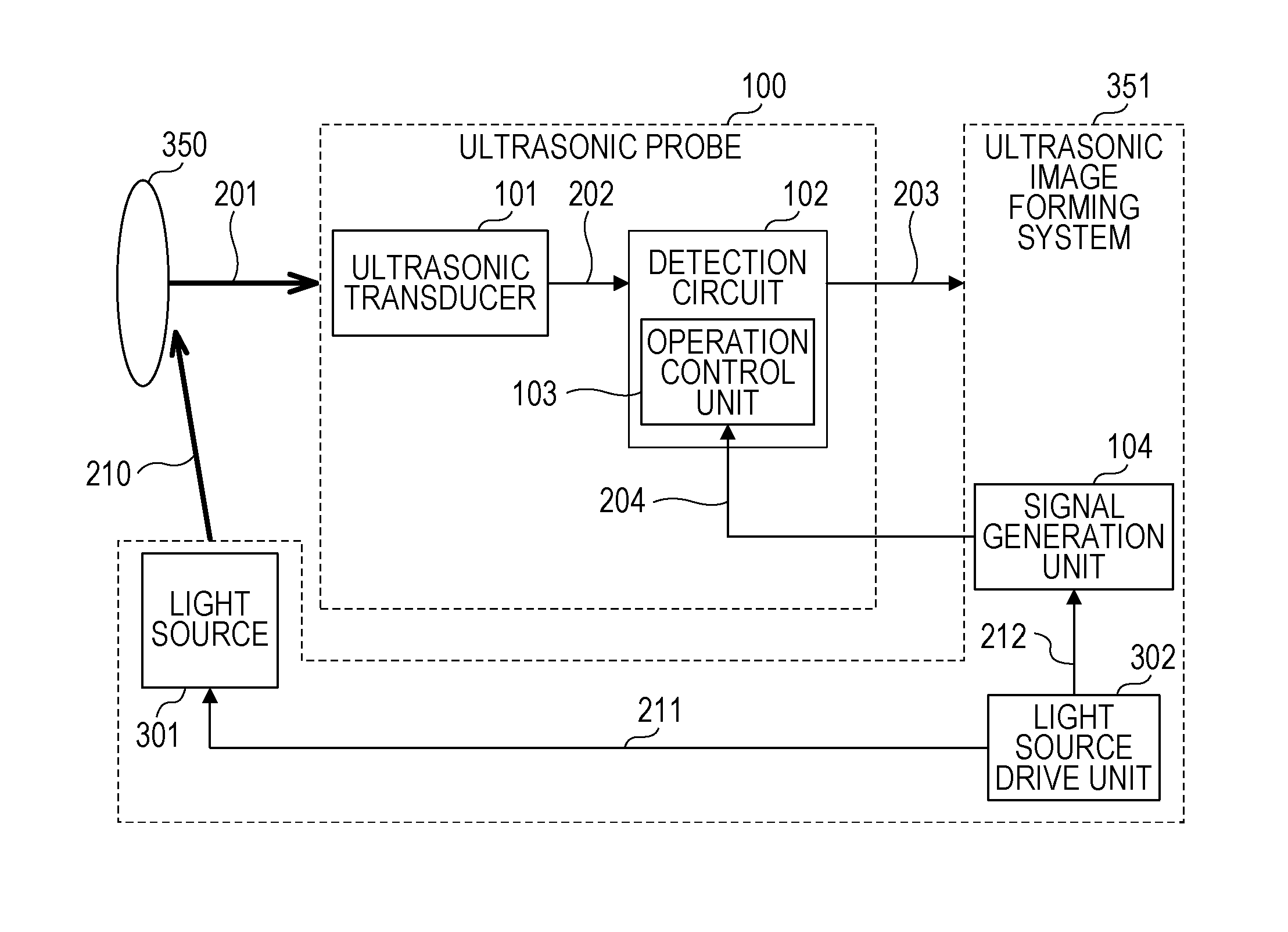
[0041]Next, a description will be given of a third exemplary embodiment by using FIGS. 3A to 3F. A difference of the third exemplary embodiment from the second exemplary embodiment resides in that an operation signal generation unit (hereinafter, which may also be referred to as signal generation unit) 104 configured to generate an operation signal. The other configuration is the same as the second exemplary embodiment. According to the present exemplary embodiment, the detection circuit 102 is caused to operate or not to operate by the operation signal 204 generated by the signal generation unit 104 in the ultrasonic probe 100. FIG. 3A is an explanatory diagram for describing configurations of the detection circuit 102 and the ultrasonic probe 100 according to the present exemplary embodiment. In FIG. 3A, the signal generation unit 104 such as a comparator or the like configured to control the switch and an ultrasonic wave generation signal 205 are illustrated.
[0042]FIGS. 3B, 3C, 3...
PUM
 Abstract
Description
Claims
Application Information