
Front vehicle-body structure of vehicle

a front vehicle and body technology, applied in the direction of vehicle components, pivoted suspension arms, resilient suspensions, etc., can solve the problems that the above-described weak portion extending in the vehicle width direction cannot be provided in some cases properly, and the space of the above-described fastening portion of the subframe may be so limited

Active Publication Date: 2014-09-11
MAZDA MOTOR CORP
View PDF5 Cites 22 Cited by
  • Summary
  • Abstract
  • Description
  • Claims
  • Application Information

AI Technical Summary

Benefits of technology

The present invention provides a front vehicle-body structure that can properly detach the rear end of the sub frame from the vehicle body in the case of a head-on collision, even if there is no weak portion in the vehicle width direction. This is achieved by configuring a bending portion and a rear extension portion that can transmit the collision load to the sub frame through a difference in direction. The suspension lower arm is also provided to ensure proper deformation and detachment of the sub frame from the vehicle body. This allows for proper handling of the collision load and ensures safety and reliability of the vehicle.

Problems solved by technology

However, this may cause a problem in that the direction of a collision load occurring in the vehicle head-on collision which is transmitted from the extension portion to the sub-frame body portion slants so greatly inward relative to the vehicle longitudinal direction that a sufficiently-large load enough to bend the portion near the rear end of the sub frame in the vehicle width direction for proper detaching of the sub frame's rear end from the vehicle body could not be transmitted by way of the extension portion.
Consequently, a space of the above-described fastening portion of the sub frame may be so limited that the above-described weak portion extending in the vehicle width direction could not be provided properly in some case.

Method used


Image

  • Front vehicle-body structure of vehicle
  • Front vehicle-body structure of vehicle
  • Front vehicle-body structure of vehicle

Examples


Embodiment Construction

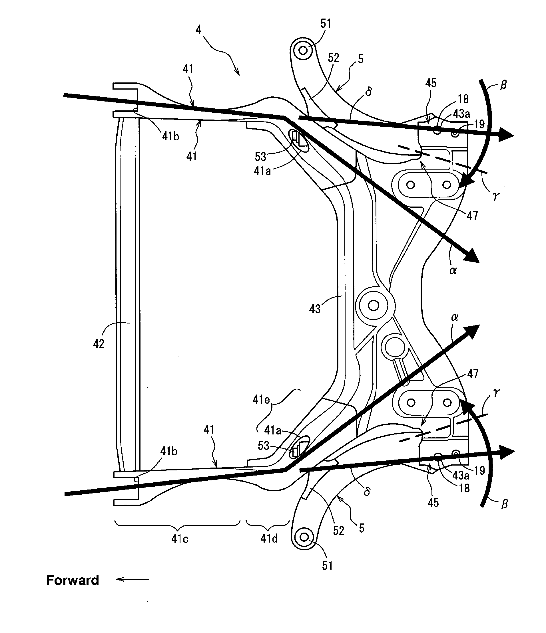
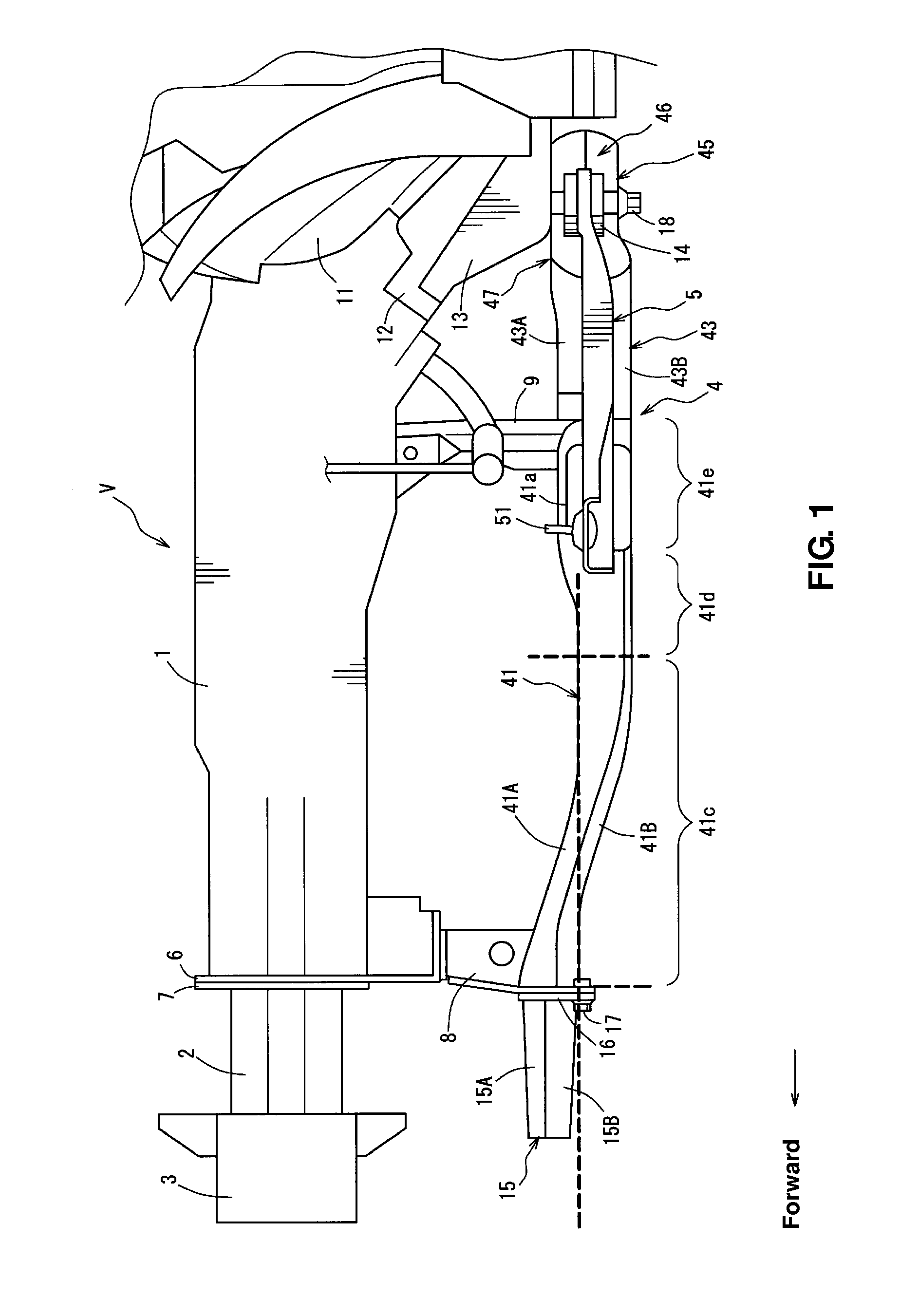
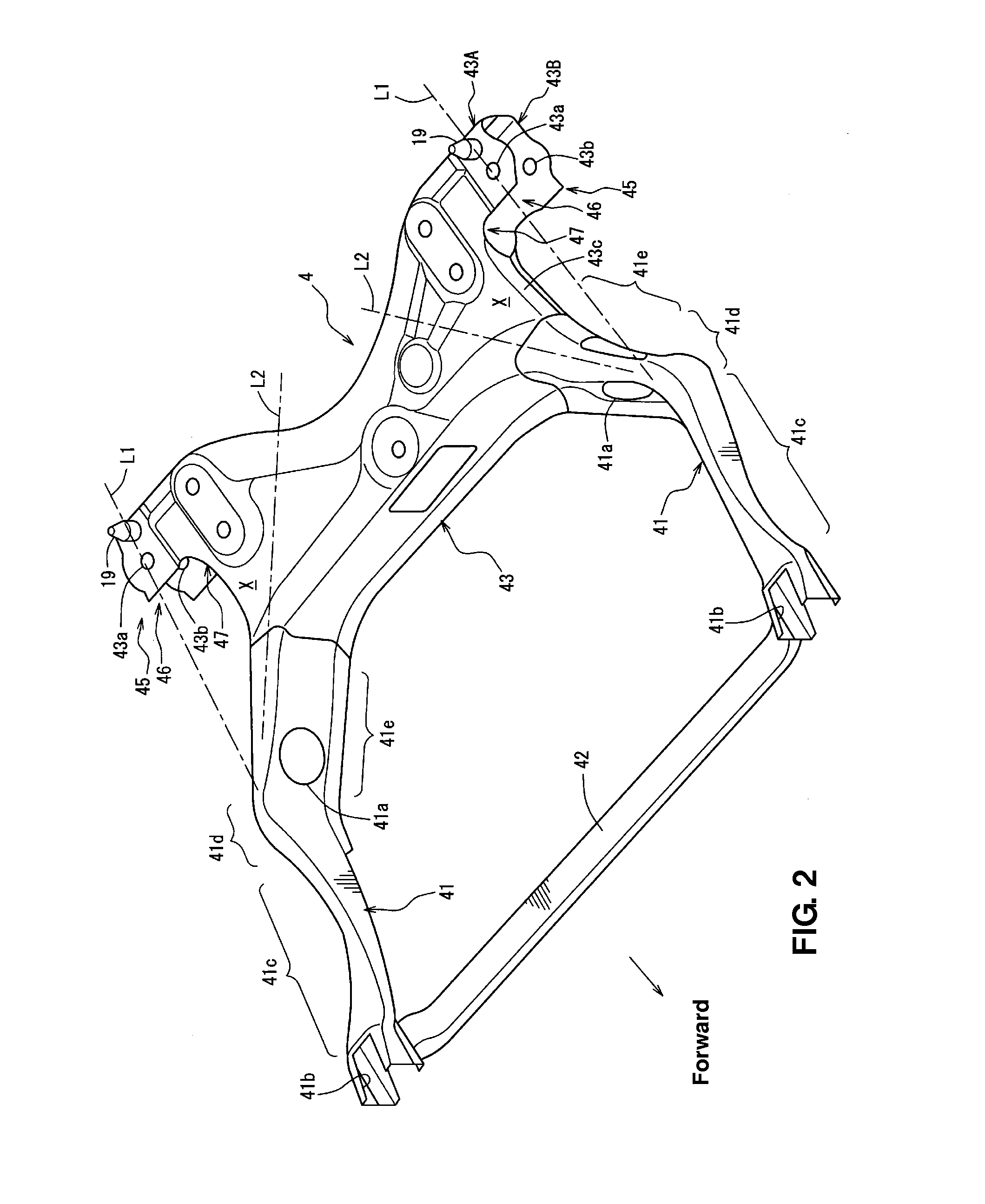
[0025]Hereinafter, an embodiment of the present invention will be described specifically referring to the drawings. FIG. 1 is a side view showing a front vehicle-body structure of a vehicle V according to the embodiment of the present invention. The vehicle V of the present embodiment is a small type of vehicle which has a short front nose. Further, the vehicle V comprises at its front portion, as shown in FIG. 1, a pair of right-and-left front side frames 1 (only its left side is illustrated in FIG. 1) which extend in a vehicle longitudinal direction, upper-side crash cans 2 which are connected to front ends of the front side frames 1, a bumper reinforcement 3 which interconnects the upper-side crash cans 2 in a vehicle width direction, a sub frame 4 which is arranged below the front side frames 1, and a pair of right-and-left lower arms 5 (only its left side is illustrated in FIG. 1) which constitute part of a suspension of the vehicle.

[0026]Each of the front side frames 1 is made...


PUM


Abstract

A longitudinal member is configured to transmit a part of a collision load occurring in a vehicle head-on collision to a suspension cross member by way of a front portion, a bending portion, and a rear portion. A lower arm, a portion of which is co-fastened to a vehicle body together with a fastening portion, is configured to transmit another part of the collision load occurring in the vehicle head-on collision to the fastening portion from the front portion. Accordingly, the rear end of the sub frame can be properly detached from the vehicle body in the vehicle head-on collision even in a case in which any weak portion extending in a vehicle width direction may not be provided.

Description

BACKGROUND OF THE INVENTION[0001]The present invention relates to a front vehicle-body structure of a vehicle which comprises a pair of right-and-left front side frames extending substantially in a vehicle longitudinal direction at a front portion of the vehicle and a sub frame provided below the front side frames and supporting a pair of right-and-left suspension lower arms which constitute part of a vehicle suspension.[0002]Conventionally, a structure in which collision energy occurring in a vehicle head-on collision is absorbed by deformation of front side frame is known. Further, a structure in which a sub frame supporting a vehicle suspension, a steering mechanism, a power train and others are provided below the front side frames is known. Herein, the sub frame comprises a sub-frame body portion and a pair of extension portions extending forward from the sub-frame body portion, which functions so as to absorb the collision energy secondarily.[0003]In the structure equipped with...

Claims


Application Information

Patent Timeline
IPC IPC(8): B62D21/15
CPCB62D21/155
Inventor OTANI, TAKAHIROSASAGE, KOHTAROHIBINO, NOBUHIKOISHIKAWA, YASUSHIKANEMOTO, SHUNSUKE
Owner MAZDA MOTOR CORP
Learn More