Window sill with rainwater channel drainage

a rainwater channel and window sill technology, applied in the direction of rain/draught deflectors, construction, building components, etc., can solve the problems of flashings, flashings of thousands of different brands, and basic flaws in the current use of windowsill systems,

Inactive Publication Date: 2014-09-18
PETTIBONE GEORGE E
View PDF9 Cites 23 Cited by
  • Summary
  • Abstract
  • Description
  • Claims
  • Application Information

AI Technical Summary

Benefits of technology

[0025]In accordance with the present invention, an improved window sill system, of the type having a sill frame un

Problems solved by technology

Window sill systems in current use have basic flaws, including but not limited to the following:
The fasteners, of thousands of different brands, types, sizes, materials, widths, of window doors, or other exterior materials to or through metal sill flashings has a long history of failure.
This is because the concept has built in flaws in

Method used


Image

  • Window sill with rainwater channel drainage
  • Window sill with rainwater channel drainage
  • Window sill with rainwater channel drainage

Examples


Embodiment Construction

[0039]In the following detailed description of the invention, certain preferred embodiments are illustrated providing certain specific details of their implementation. However, it will be recognized by one skilled in the art that many other variations and modifications may be made given the disclosed principles of the invention.

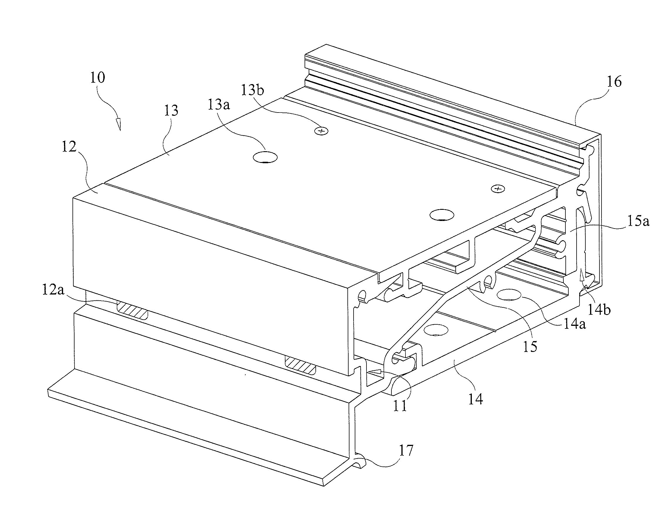
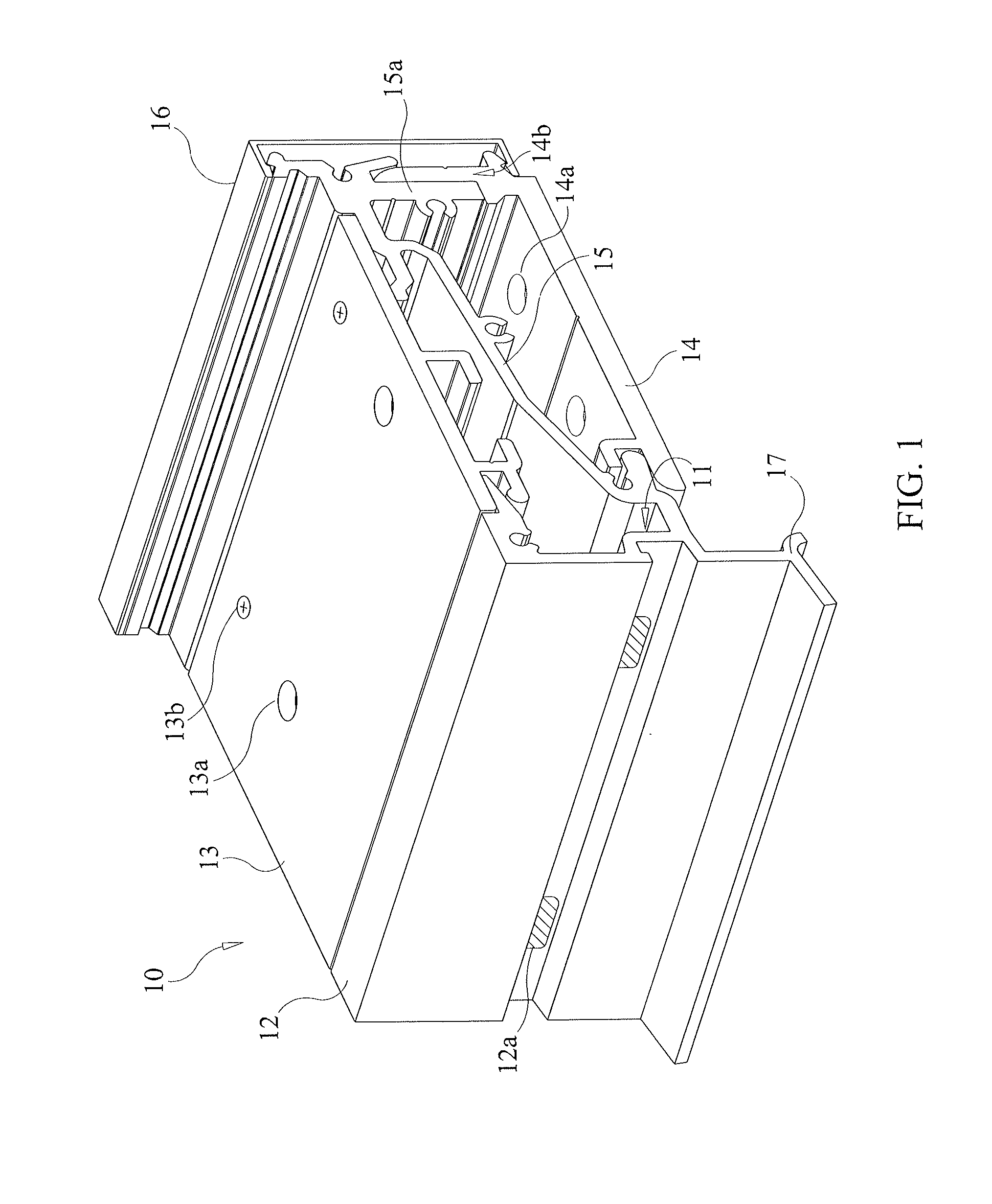
[0040]Referring to FIG. 1, an isometric sectional view of a preferred embodiment shows the unique structure of a bottom frame of an improved window sill system in accordance with the present invention. The bottom frame is part of a quadrangular sill frame unit having a top frame (not shown), bottom frame 10, and opposite lateral frames (not shown) forming a rectangular opening for a window therein. In the bottom frame 10 shown, a water trough or channel 11 is formed extending across a length of the bottom frame of the sill system at a front edge 12 facing outwardly of a window in which the sill system is to be installed. On a top side a channel space opposite...


PUM


Abstract

An improved window sill system has a bottom frame structure that is part of a sill frame unit. The bottom frame has a water trough or channel extending across its length at a front edge facing outwardly of a window in which the sill system is to be installed. The water trough or channel has a top plate provided with a plurality of weep holes for capturing rainwater dripping down the window into the water trough or channel. A base plate is provided with screw holes for mounting the bottom frame to a surrounding window frame. An inner deflection wall deflects water captured in the water trough or channel from the screw holes for mounting the bottom frame of the sill system to the window frame.

Description

[0001]This U.S. patent application claims priority to U.S. Provisional Application Ser. No. 61 / 780,837 filed on Mar. 13, 2013, the contents of which are herein incorporated by reference in its entirety.BACKGROUND OF INVENTION[0002]Window sill systems in current use have basic flaws, including but not limited to the following:[0003]A. Sheet metal, plastic, rubber or synthetic membrane, stainless steel sheets, aluminum extrusions, must be fastened to the building by some mechanical form, such as screws or bolts, nails or all threaded rods.[0004]B. Most of these fasteners end up in what is referred to as the “wet-zone” which where we expect to capture some amount of moisture / water and keep it from entering the building envelope. Holes are drilled in these conventional window sill flashings for these fasteners. Sealant is normally applied to the head of fasteners to try to keep surroundings standing water from seeping through the holes and into the building substrate. Expansion and cont...

Claims


Application Information

Patent Timeline
IPC IPC(8): E06B7/14E06B7/26E06B1/70
CPCE06B7/14E06B7/26E06B1/702
Inventor PETTIBONE, GEORGE E.
Owner PETTIBONE GEORGE E
Why Eureka
Try Eureka