Endotrachael Tube Holding Device with Bite Block

a technology of holding device and endotracheal tube, which is applied in the field of endotracheal tube holding device with bite block, can solve the problems of restricting or closing off the airway within the tube, not revealing the inclusion of cheek pads and cheek plates, and patients may bite hard or clamp on the et tube with teeth or gums,

Inactive Publication Date: 2014-09-18
HOLLISTER INCORPORAED
View PDF7 Cites 16 Cited by
  • Summary
  • Abstract
  • Description
  • Claims
  • Application Information

AI Technical Summary

Benefits of technology

[0010]In one example according to the teachings of the present invention, a device for holding an endotracheal tube to a patient has a track configured to fit adjacent a lip on a patient's face. The track has a face contacting side, an exposed side opposite the face contacting side, and a pair of opposite ends. A tube holder is coupled to and slidable along the track between the opposite ends. A positioning mechanism is releasably lockable to allow selective lateral repositioning of the tube holder and an endotracheal tube held thereby along the track and to retain the tube holder at a selected position along the track. A bite block is carried by the tube holder and is slidable therewith along the track. The bite block has a tubular wall, a central opening along a length of the bite block, an interior wall surface, and a pair of opposite open ends. The bite block is positioned spaced vertically from the track. One of the opposite ends if the bite block is a working end portion that extends in the direction of and further beyond the face contacting side of the track. An accessory line channel is positioned between the interior wall surface and an endotracheal tube that extends through the central opening.

Problems solved by technology

However, the '504 patent does not disclose inclusion of the cheek pads and cheek plates.
One problem with these and other known ET tube holding devices is that the patient may sometimes bite down hard or clamp onto the ET tube with their teeth or gums (denture wearers).
This can restrict or close off the airway within the tube.
These known products are generally large, cumbersome, and complicated devices that can be difficult to manipulate and install.
Another problem with these types of ET tube holding devices is that the tube often is accompanied by one or more accessory lines that also pass into the patient.

Method used


Image

  • Endotrachael Tube Holding Device with Bite Block
  • Endotrachael Tube Holding Device with Bite Block
  • Endotrachael Tube Holding Device with Bite Block

Examples


Embodiment Construction

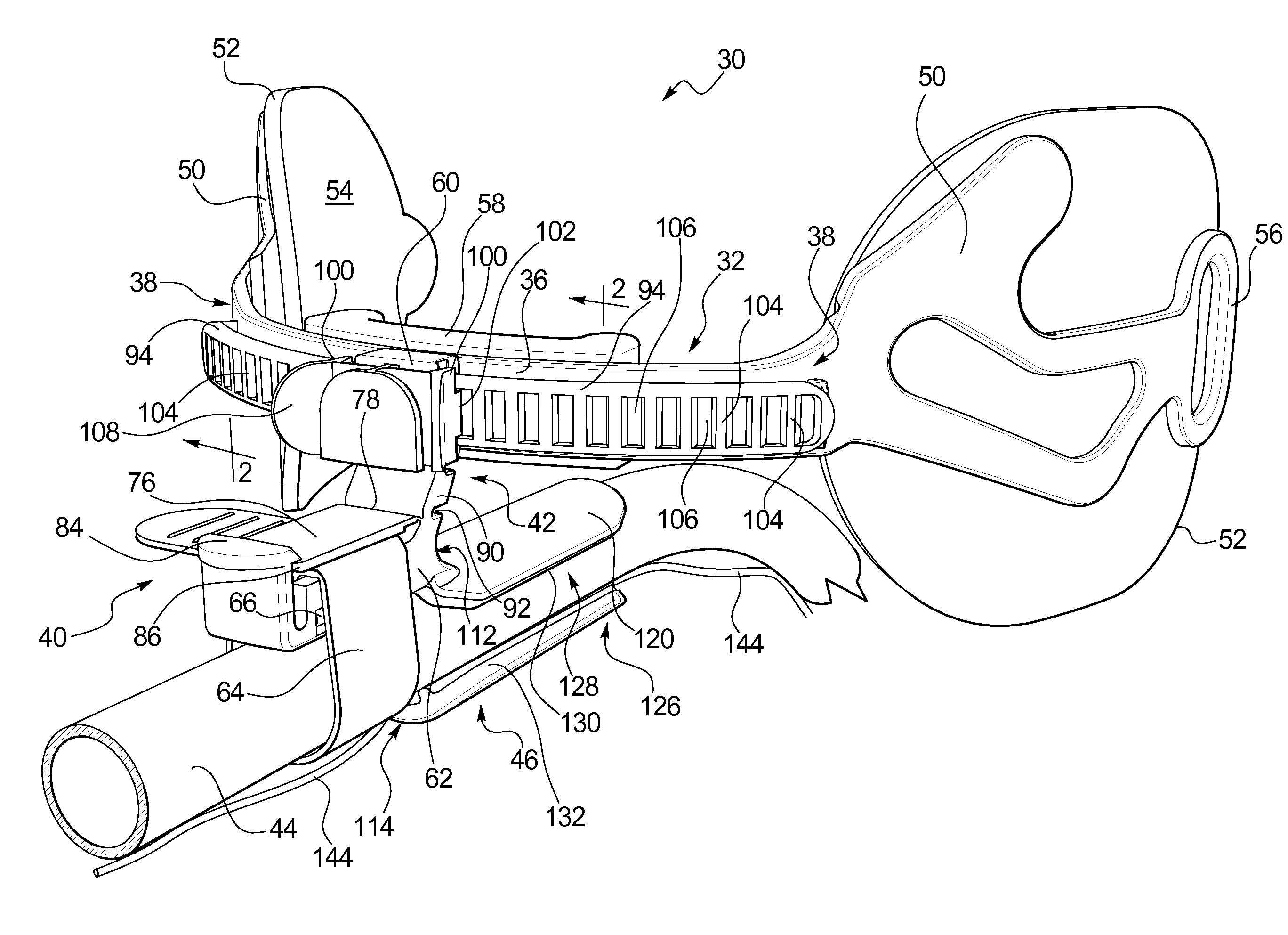
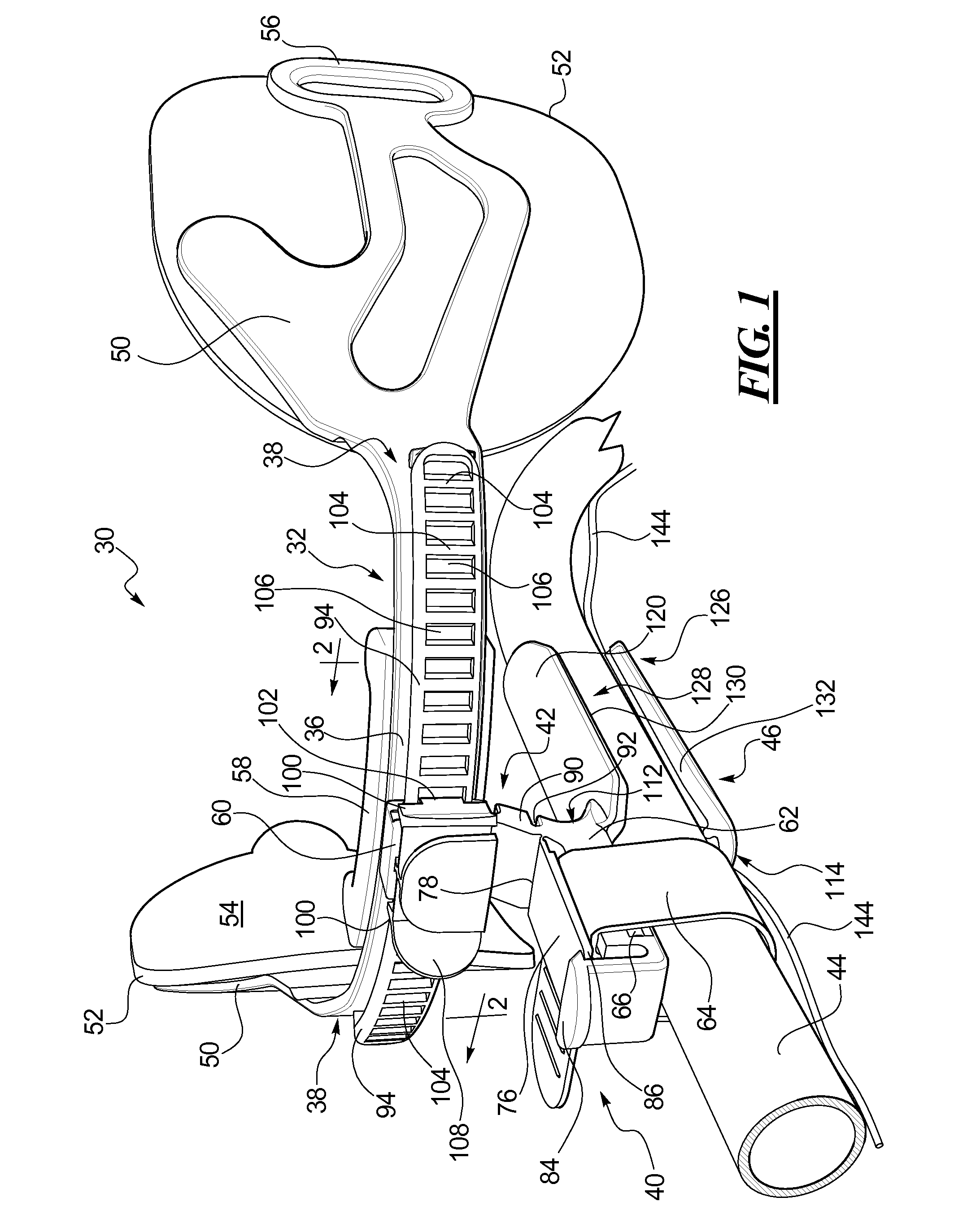
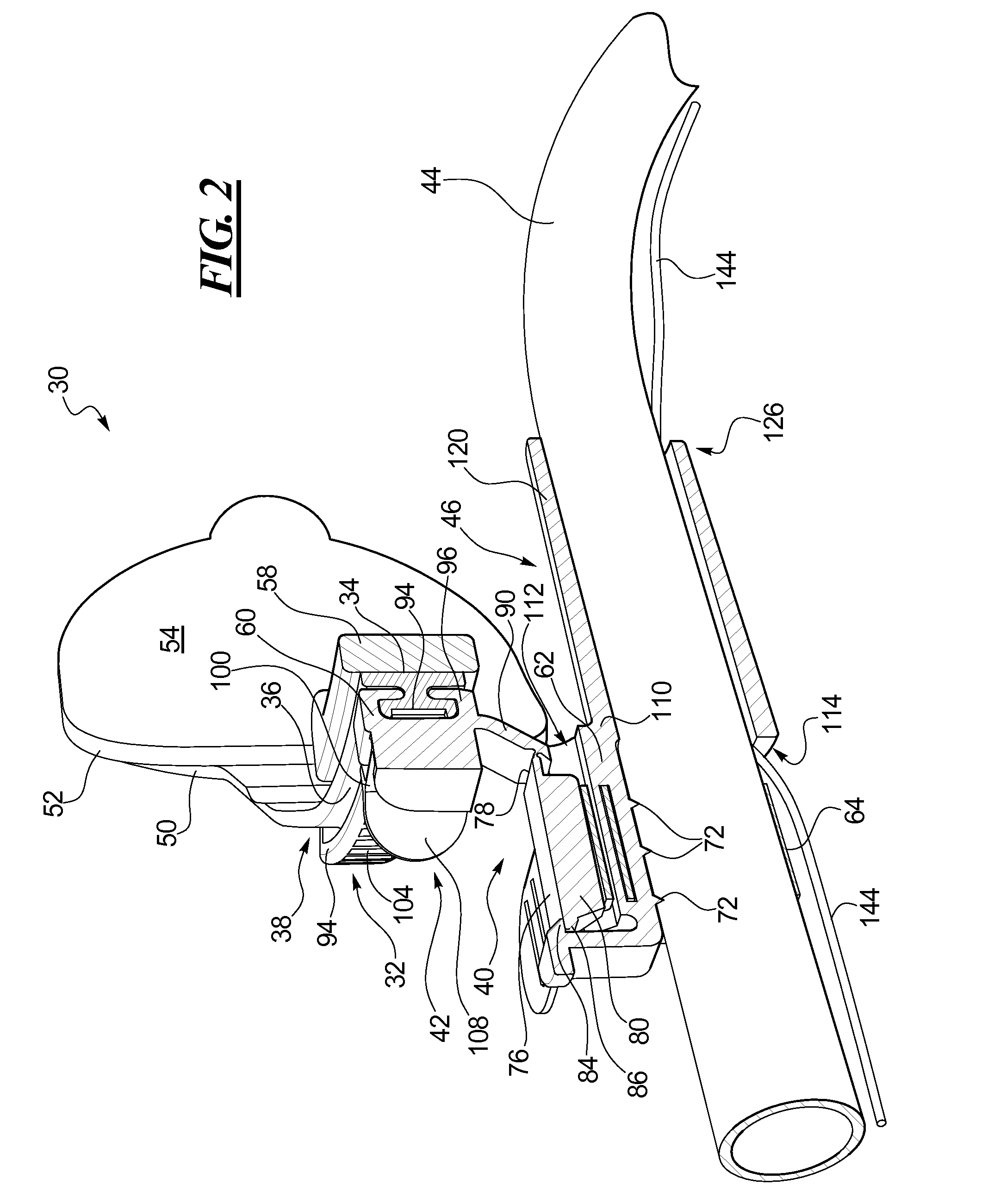
[0086]The disclosed ET tube holding devices solve or improve upon one or more of the above-noted and / or other problems and disadvantages with prior know ET tube holding devices. In one example, the disclosed devices have a bite block integrated into a tube holder portion of the device. In one example, the disclosed devices have a tube holder that is side-to-side adjustable along with an ET tube secured by the device and a bite block integrated into the tube holder. In one example, the disclosed devices have a bite block that is integrally molded as a part of the tube holder. In one example, the disclosed devices have a bite block with one or more features to assist in inserting an ET tube, retaining the ET tube in position once inserted, and accommodating an accessory line that passes within the bite block but outside of the ET tube. These and other objects, features, and advantages of the present invention will become apparent to those having ordinary skill in the art upon reading ...


PUM


Abstract

A bite block for an endotracheal tube has a tubular wall with a pair of opposed ends, a central opening along a length of the bite block between the pair of opposed ends, an interior wall surface, and an accessory line channel positioned between the interior wall surface and an endotracheal tube extending through the central opening. The accessory line channel is formed by a wall segment that is recessed into the interior wall surface, the wall segment being thinner than a thickness of the tubular wall adjacent the wall segment. The bite block can be part of or attachable to an endotracheal tube holding device attachable to a patient.

Description

RELATED APPLICATION DATA[0001]This patent is a continuation-in-part of and claims priority benefit of co-pending U.S. patent application Ser. No. 13 / 840,375 filed Mar. 15, 2013 and entitled “Endotracheal Tube Holding Device with Bite Block.” This prior filed application is hereby incorporated by reference herein in its entirety.BACKGROUND[0002]1. Field of the Disclosure[0003]The present invention is generally directed to medical tube devices, and more particularly to a device for holding an endotracheal tube on a patient and having a bite block integrated with the device.[0004]2. Description of Related Art[0005]Endotracheal (ET) tubes are commonly inserted through the mouth and into the trachea of patients under critical care. The ET tube is used to maintain an open airway for the patient to breathe and to allow mechanical assistance of breathing. ET tubes are often placed prior to surgery or are used on trauma or critically ill patients that may require intubation for extended peri...

Claims


Application Information

Patent Timeline
Patent Type & Authority Applications(United States)
IPC IPC(8): A61M16/04
CPCA61M16/0493A61M16/0463A61M16/0497A61M25/02A61M2025/022A61M2025/0253A61B1/00154
Inventor VISCONTI, PETER L.LEADINGHAM, BRIAN T.TETZLAFF, PATRICK C.WISNER, PAOLA M.HANTKE, RICHARD J.SHANAHAN PHEIL, MEAGAN R.KNAUZ, DAVIS A.BERGER, CHERYL D.CISKO, GEROGE J.DANG, THAI H.GILMAN, THOMAS H.MEADE, NOAH K.CHUNG, TZE WAN PANSYAUGUSTYN, CHRISTINAMARCH, DANIEL A.MCDONOUGH, DAVIDBARKER, JAMES BRANDON
Owner HOLLISTER INCORPORAED
Why Eureka
Try Eureka