Welding gooseneck with variable radius

a technology of variable radius and gooseneck, which is applied in the direction of shielding support devices, electrode supporting devices, manufacturing tools, etc., can solve the problems of electrode loss, electrode rigidity loss, and tip also creating more drag on the electrod

Inactive Publication Date: 2014-09-18
LINCOLN GLOBAL INC
View PDF6 Cites 19 Cited by
  • Summary
  • Abstract
  • Description
  • Claims
  • Application Information

AI Technical Summary

Problems solved by technology

However, increasing pressure between the electrode and the contact tip also creates more drag on the electrode as it is fed through the gun.
This results in the electrode losing rigidity and becoming more susceptible to feeding problems.
Common feeding problems include slipping at the drive rolls that feed the electrode or buckling of the electrode after it leaves the drive rolls.
A reverse bend near the contact tip can also make feeding of a smaller and less rigid electrode more difficult due to bending or kinking of the electrode wire as it is fed through the bend.

Method used


Image

  • Welding gooseneck with variable radius
  • Welding gooseneck with variable radius
  • Welding gooseneck with variable radius

Examples


Embodiment Construction

[0018]The best mode for carrying out the invention will now be described for the purposes of illustrating the best mode known to the applicant at the time of the filing of this patent application. The examples and figures are illustrative only and not meant to limit the invention, which is measured by the scope and spirit of the claims.

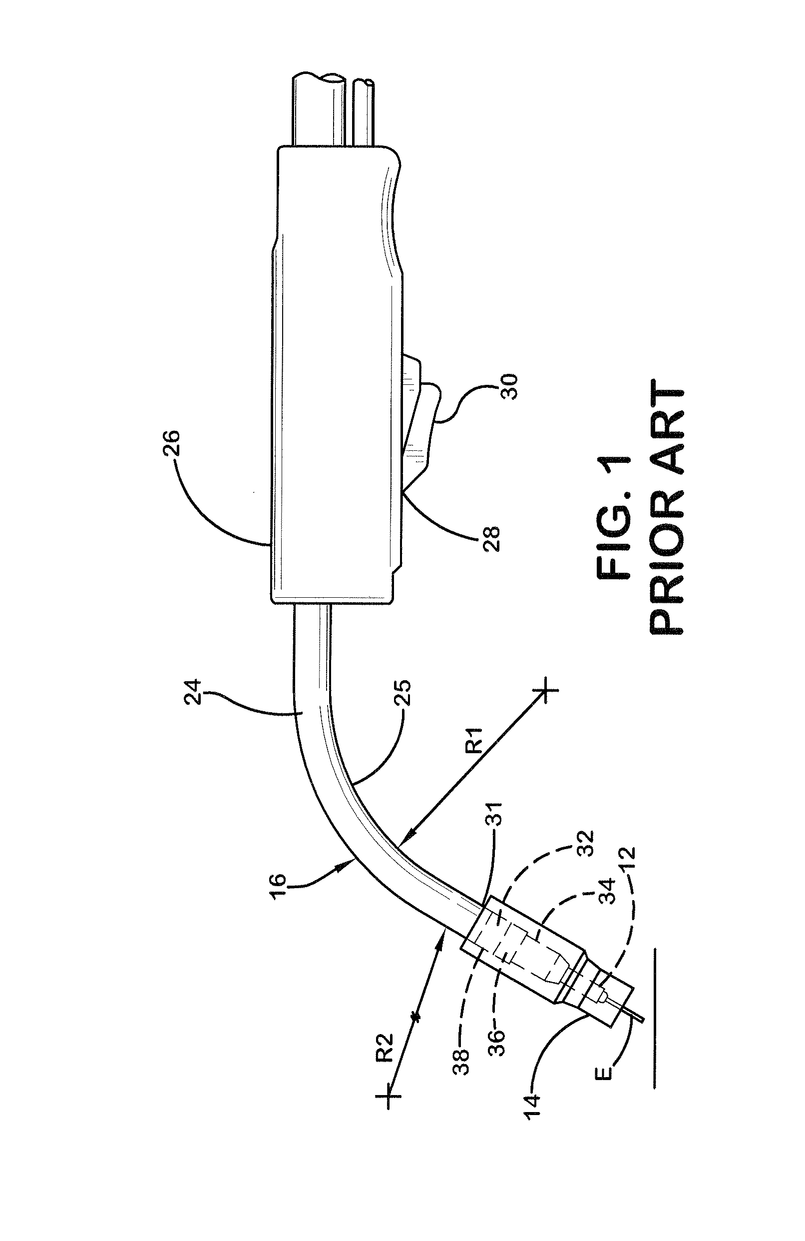
[0019]Referring to FIG. 1, a prior art welding gun nozzle is shown having a reverse bend in the nozzle on an end of a nozzle tube which extends to the left in an arcuate manner to guide electrode E and shielding gases to contact tip 12 and gas nozzle 14. Gooseneck tube 16 is formed of high conductivity copper material and is generally cylindrical in its external shape, although it may be any shape. Tube 16 can have an internal non-cylindrical passage such as a polygonal shape, preferably square, although most internal passages are round. Inside of the passage is a cylindrical steel tube and a cylindrical electrode wire guide formed of extruded plastic...


PUM

PropertyMeasurementUnit
radiusaaaaaaaaaa
radiiaaaaaaaaaa
conductiveaaaaaaaaaa

Abstract

The invention described herein generally pertains to a variably radiused curvilinear gooseneck nozzle for a welding torch.

Description

TECHNICAL FIELD[0001]The invention described herein pertains generally to welding torch goosenecks having a non-fixed or variable radius.BACKGROUND OF THE INVENTION[0002]A substantial amount of arc welding is now done industrially by the use of robotic and automatic welding equipment wherein a supply of welding wire is pulled from a drum by a wire feeder and pushed through a welding cable and then through a welding gun movable along a workpiece. The robot performs a continuous welding operation. The welding torch includes a tubular contact tip allowing a welding current to be conducted to the wire moving through a wire receiving passage in the contact tip so the current between the wire and workpiece melts the wire for deposition of the metal onto the workpiece. This robotic or automatic type welding equipment operates continuously over many hours repeating the same welding operation. Thus, it is essential that the moving welding wire be provided to the welding operation while advan...

Claims


Application Information

Patent Timeline
Patent Type & Authority Applications(United States)
IPC IPC(8): B23K9/12B23K9/29
CPCB23K9/295B23K9/123B23K9/287
Inventor ENYEDY, EDWARD A.SADOWSKI, GRANT TAYLORMEESS, BRIAN DAVIDKACHLINE, JEFFREY L.
Owner LINCOLN GLOBAL INC
Why Eureka
Try Eureka